Crane Box Girder Design: Capacity, Span, Structure and Applications
Content Quick Link
What Is a Crane Box Girder?
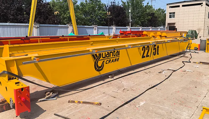
A crane box girder is a closed-section steel beam used as a main structural member in overhead cranes and gantry cranes. It supports the loads generated by the hoist, trolley, and lifted materials while providing the strength and stiffness required for crane operation.
Unlike an open I-beam, a box girder typically consists of top and bottom plates joined by two side webs, forming a closed cross-section. Internal diaphragms and stiffeners may be added to improve local stability and transfer concentrated loads.
Box girders are used in selected single-girder and double-girder overhead cranes, as well as gantry cranes for heavy industrial lifting. The appropriate configuration depends on the required capacity, span, trolley arrangement, operating duty, and structural design requirements.
How Does a Box Girder Differ from an I-Beam?
| Feature | Box Girder | I-Beam |
|---|---|---|
| Cross-section | Closed, usually rectangular | Open, with two flanges and a web |
| Structural behavior | Can provide high torsional rigidity | Efficient in bending about its strong axis; torsional behavior requires assessment |
| Construction | Typically fabricated from welded steel plates | May use a standard rolled section or welded plates |
| Typical applications | Selected heavy-duty, double-girder, and gantry crane designs | Suitable monorail, underslung, and other crane configurations |
| Design considerations | Plate stability, weld quality, internal details, and inspection access | Flange and web behavior, lateral stability, and torsional effects |
Where Are Crane Box Girders Used?
- Single-girder overhead cranes: A box-section main girder may be selected when its structural properties suit the required loads and crane arrangement.
- Double-girder overhead cranes: Two main girders commonly support a trolley and hoist operating above the bridge girders.
- Gantry cranes: Box girders can form the main bridge structure, with the design coordinated with the gantry legs, end trucks, rails, and foundations.
Why Does Box Girder Geometry Matter?
The width, height, plate thickness, and internal reinforcement of a box girder affect its bending resistance, torsional rigidity, local plate stability, and overall weight.
A properly designed box girder can provide the stiffness and structural performance required for demanding lifting applications. However, a closed section is not automatically stronger or more economical in every situation. The final design must account for crane span, rated capacity, trolley wheel loads, duty class, deflection limits, fatigue, and the applicable design standard.
Box Girder Cross-Section and Structural Components
A welded box girder is a closed-section steel beam fabricated from steel plates joined by welding. Its structural performance depends on how the plates, internal diaphragms, stiffeners, and welded joints work together to resist bending, shear, and torsional loads.
The exact cross-section varies with crane capacity, span, trolley arrangement, wheel loads, and design requirements. The following components are commonly considered in box girder design.
Main Components of a Welded Box Girder
| Component | Main Function |
|---|---|
| Top and bottom plates | Contribute to bending resistance by carrying longitudinal stresses in the girder. |
| Side webs | Transfer shear forces and connect the top and bottom plates. |
| Internal diaphragms | Help maintain cross-sectional shape and transfer concentrated loads between structural elements. |
| Stiffeners | Improve local plate stability and help resist localized stresses where required. |
| Welded joints | Connect the plates and transfer structural forces between components. Weld quality is essential to structural integrity and fatigue performance. |
| Rail or trolley support | Transfers trolley wheel loads or other equipment loads into the girder structure. The arrangement depends on the crane configuration. |
How Do These Components Work Together?
The top and bottom plates and side webs form the main closed section. Together, they provide bending resistance and torsional rigidity. Internal diaphragms and stiffeners help control local deformation and maintain stability under concentrated loads, while welded joints connect the structural elements so that they act together.
The trolley or rail support arrangement is also important because wheel loads must be transferred into the girder without causing unacceptable local stresses or deformation. Its design depends on whether the trolley runs on top of the girders, between them, or in another configuration.
Engineering consideration: A larger box section does not automatically guarantee a better crane girder. Plate thickness, section proportions, weld details, internal reinforcement, deflection limits, fatigue requirements, and inspection access must all be considered during design.
How Is a Welded Box Girder Fabricated?
A welded box girder is manufactured by cutting, assembling, and welding steel plates into a closed structural section. Each step ensures the girder meets the required strength, dimensions, and quality standards.
Manufacturing Process
| Step | Process | Key Check |
|---|---|---|
| 1. Plate preparation | Cut steel plates and prepare edges for welding. | Material grade, thickness, and dimensions |
| 2. Assembly | Fit the top and bottom plates, side webs, diaphragms, and stiffeners. | Component alignment |
| 3. Welding | Weld the plates together using approved procedures. | Weld quality and distortion control |
| 4. Inspection | Check welds and overall girder dimensions. | Defects, straightness, and dimensional tolerances |
| 5. Finishing | Prepare the surface, apply protective coating, and check connection points. | Coating condition and assembly fit |
Why Does Fabrication Quality Matter?
| Quality Factor | Importance |
|---|---|
| Weld quality | Ensures reliable load transfer between components. |
| Distortion control | Keeps the girder straight and correctly aligned. |
| Dimensional accuracy | Ensures proper fit with the trolley and crane structure. |
| Material traceability | Links steel materials to manufacturing and inspection records. |
| Protective coating | Helps prevent corrosion during service. |
Buyer tip: Ask the crane manufacturer about its welding procedures, inspection methods, dimensional checks, material traceability, and coating specifications before confirming your order.
Why Is a Box Girder Used for Heavy-Duty Cranes?
Box girders are used in selected heavy-duty cranes because their closed-section structure provides torsional rigidity and bending stiffness. However, the best girder type depends on calculated loads, span, crane configuration, and project requirements.
| Engineering Factor | Why It Matters |
|---|---|
| Torsional rigidity | The closed section resists twisting under uneven or eccentric loads. |
| Bending strength and stiffness | The section helps support lifting loads while controlling deflection. |
| Heavy-duty applications | Suitable for selected large-capacity cranes and demanding operating conditions. |
| Trolley integration | Can accommodate trolley rails and double-girder arrangements according to the design. |
| Cost and maintenance | Plate fabrication, welding, structural weight, inspection access, and maintenance requirements affect the overall cost. |
Key point: A box girder is not automatically required for every heavy or long-span crane. Engineers must compare structural performance, weight, fabrication cost, and operating requirements before selecting the girder type.
Crane Box Girder Capacity: What Determines the Load Rating?
Crane capacity cannot be determined from box girder dimensions alone. The design must consider the lifted load, trolley weight, wheel loads, span, operating duty, and applicable structural requirements.
| Design Factor | What Engineers Check |
|---|---|
| Rated lifting capacity | Maximum rated load handled by the crane. |
| Hoist and trolley weight | Additional loads acting on the main girders. |
| Girder dimensions | Section height, width, plate thickness, and internal reinforcement. |
| Span and wheel positions | Bending moments, shear forces, and load distribution. |
| Structural performance | Bending strength, local plate stability, and deflection limits. |
| Duty class and standards | Repeated loading, fatigue requirements, and applicable design criteria. |
Buyer Checklist for Box Girder Design
Provide the following information for a project-specific assessment:
- Rated lifting capacity and hoist/trolley arrangement.
- Crane span and runway layout.
- Lifting height and available headroom.
- Duty class or expected operating frequency.
- Operating environment, including outdoor exposure or corrosive conditions.
- Applicable design standards and project requirements.
- Existing runway drawings and available wheel-load limits, if applicable.
Box Girder Span: How Does Span Affect Design?
As crane span increases, the girder generally requires closer evaluation of bending, deflection, stability, self-weight, and supporting runway loads. A longer span may also increase fabrication, transportation, and installation costs.
| Engineering Check | Shorter Span | Longer Span |
|---|---|---|
| Bending and deflection | Verify against design limits. | Often requires greater attention to stiffness and deflection. |
| Girder self-weight | Include in structural calculations. | Weight may increase and add to runway wheel loads. |
| Torsional and lateral stability | Check for the selected configuration. | Assess stability and load distribution carefully. |
| Fabrication and transport | Check manufacturing and delivery constraints. | Evaluate transport dimensions, lifting, and site assembly. |
| Installation | Confirm access and erection requirements. | Coordinate lifting equipment, site access, and installation procedures. |
Important: A long span does not automatically require a box girder. Selection depends on the calculated loads, allowable deflection, crane configuration, and comparison with alternative girder designs.
Box Girder for Double-Girder Overhead Cranes
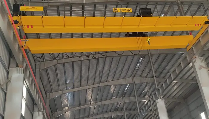
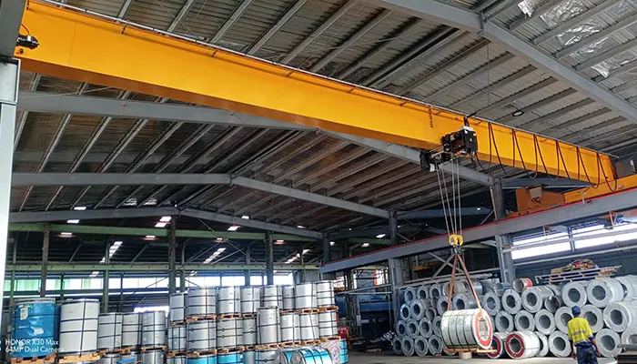
A double-girder overhead crane typically uses two parallel main girders connected by end carriages. A trolley carrying the hoist travels along rails mounted on top of the girders, although the exact arrangement varies by design.
Main Components and Load Transfer
| Component | Function |
|---|---|
| Two main box girders | Support the trolley and transfer loads to the end carriages. |
| Trolley rails | Provide the running surface for trolley wheels. |
| Trolley and hoist | Lift and move materials across the crane span. |
| End carriages | Transfer bridge loads to the runway wheels. |
| Runway rails and supporting structure | Carry crane wheel loads into the building structure or supporting system. |
During lifting, the load passes from the hoist to the trolley wheels, through the rails and main girders, and into the end carriages and runway. Engineers must check wheel loads, fatigue, girder deflection, and runway compatibility.
Lifting height, hook approach, and available headroom also influence the arrangement of the trolley, hoist, and girders.
Box Girder for Gantry Cranes
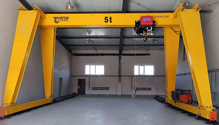
Box girders can serve as the main bridge beams of rail-mounted gantry cranes and other outdoor lifting systems. Their design must account for both lifting loads and the forces generated by gantry travel and environmental conditions.
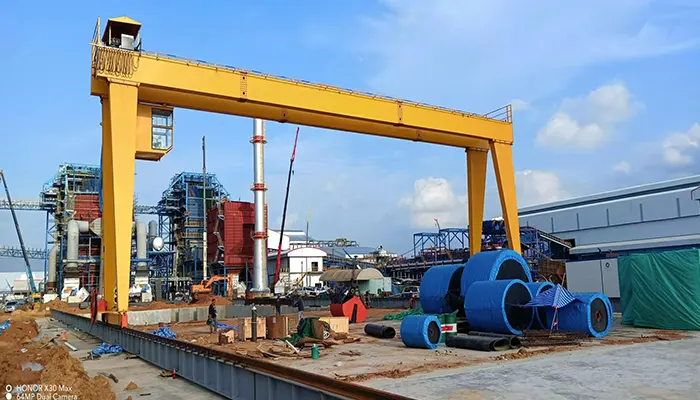
| Design Factor | Key Consideration |
|---|---|
| Main girder and leg connections | Transfer loads between the bridge, gantry legs, and supporting structure. |
| Rail gauge and wheel loads | Affect stability, load distribution, and rail or foundation requirements. |
| Wind and environmental loads | Important for outdoor cranes and must be evaluated under applicable design criteria. |
| Corrosion protection | Coating systems and maintenance access should suit the operating environment. |
| Transportation and erection | Girder dimensions, lifting arrangements, site access, and assembly methods affect project planning. |
| Foundation coordination | Wheel loads and crane reactions must be coordinated with the rail system and foundations. |
Typical Applications
Box girder gantry cranes may be used in:
- Ports and container-handling facilities.
- Shipyards and heavy fabrication yards.
- Steel storage and processing yards.
- Hydropower facilities and dam-related projects.
- Large industrial plants and outdoor material-handling areas.
The final design depends on lifting capacity, span, rail gauge, duty class, wind exposure, travel requirements, and site conditions.
Box Girder vs. I-Beam: Key Differences
Box girders and I-beams serve different crane design requirements. The right choice depends on structural loads, span, trolley arrangement, fabrication cost, and maintenance needs.
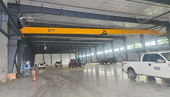
5 ton overhead crane with box girder design
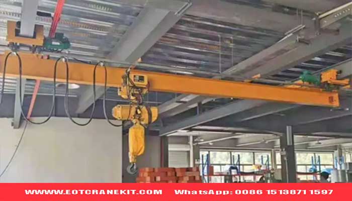
| Comparison Factor | Box Girder | I-Beam |
|---|---|---|
| Cross-section | Closed section | Open section |
| Torsional behavior | Generally offers higher torsional rigidity | Requires assessment of torsion and lateral stability |
| Structural weight | Depends on section dimensions and plate thickness | May be lighter for suitable applications |
| Deflection | Depends on section geometry and loading | Depends on section geometry and loading |
| Fabrication | Typically assembled and welded from steel plates | May use a standard rolled section or welded plates |
| Inspection and maintenance | Internal inspection access may need consideration | Open profile generally provides easier visual access |
| Total cost | Includes plate fabrication, welding, inspection, and coating | Depends on section availability, fabrication, and reinforcement needs |
| Typical selection | Selected heavy-duty, double-girder, and gantry crane designs | Suitable where an open section meets structural requirements |
Selection tip: Compare both options using the same design loads, deflection limits, duty requirements, and applicable standards. The lowest initial fabrication cost does not necessarily mean the lowest total project cost.
When Is a Box Girder the Better Choice?
A box girder may be preferred when the crane design requires high torsional rigidity, specific trolley rail arrangements, or a closed-section structure suited to the calculated loads. It can be a suitable option for selected heavy-duty overhead cranes and gantry cranes.
However, an I-beam may be more economical when its structural performance meets the project requirements. The final decision should be based on engineering calculations and total project cost.
Crane Girder Selection Checklist
Before choosing a box girder, confirm the following:
- Rated capacity and span: Required lifting load and distance between supports.
- Duty class and service life: Operating frequency and expected loading cycles.
- Hoist and trolley arrangement: Trolley type, lifting height, hook approach, and available headroom.
- Wheel loads and runway: Maximum wheel loads, runway capacity, and existing structural conditions.
- Operating environment: Indoor or outdoor use, corrosion exposure, and other site conditions.
- Applicable standards: Project specifications and required design criteria.
- Total project cost: Fabrication, inspection, transport, installation, and maintenance.
Need a Box Girder Design for Your Crane Project?
Submit your crane capacity, span, lifting height, duty class, hoist/trolley arrangement, and available layout or runway drawings. Yuantai Crane can review your requirements and recommend a suitable girder configuration for engineering evaluation and quotation.
FAQs About Crane Box Girder Design
Box girders are closed-section steel beams used as main structural members on overhead cranes. The following questions and answers cover their application, capacity calculation, inspection, and selection considerations.
What is a box girder on an overhead crane?
A box girder is a closed-section steel beam made from welded plates. It serves as a main structural member, supporting crane loads and providing bending stiffness and torsional rigidity.
Why are box girders used on heavy-duty cranes?
Box girders offer high torsional rigidity and can provide the strength and stiffness required for selected heavy-duty and large-capacity crane designs. Their suitability depends on the calculated loads and structural requirements.
How is crane box girder capacity calculated?
Engineers evaluate rated lifting capacity, trolley and hoist weight, crane span, wheel loads, plate dimensions, bending, shear, deflection, fatigue, and applicable design standards. Girder dimensions alone cannot determine the crane's rated capacity.
Does a longer crane span require a box girder?
No. A longer span increases the need to assess bending, deflection, structural stability, girder weight, and runway loads, but it does not automatically require a box girder. The final selection depends on engineering calculations and project requirements.
What is the difference between a single box girder and a double box girder crane?
A single-girder crane has one main bridge girder, while a double-girder crane has two parallel main girders. The choice affects trolley arrangement, lifting height, structural loading, and overall crane configuration. Either configuration must be designed for its intended application.
How are welded box girders inspected?
Inspection typically includes visual examination of welds and checks of girder dimensions, straightness, and alignment. Non-destructive testing, such as ultrasonic testing, may also be required depending on the design, inspection plan, and applicable standards.
Is a box girder stronger than an I-beam?
Not in every application. A box girder generally offers greater torsional rigidity, while an I-beam may provide an efficient and economical solution for suitable loading conditions. Both must be evaluated against the same structural design requirements.
What information is required for a custom box girder crane quotation?
Provide the rated lifting capacity, crane span, lifting height, duty class, hoist and trolley arrangement, power supply, operating environment, and applicable standards. Existing runway drawings, wheel-load limits, and site layout drawings are also helpful for engineering review.

Article by Bella ,who has been in the hoist and crane field since 2016. Bella provides overhead crane & gantry crane consultation services for clients who need a customized overhead travelling crane solution.Contact her to get free consultation.
Yuantai Cranes
Overhead Crane Manufacturer with CE, ISO, SGS, CNEX Certificates.
- Main Specifications - Capacity: 0.5–550 tons | Span: up to 40m | Speed: 0.8–12 m/min | Duty: A3–A7 | Power: 380–690V, 50/60Hz | Control: pendant/remote/cabin
- Full engineering: FEA/PLC/VFD + in-house build + global delivery + on-site support, for workshops, factories, EPC contractors, industrial projects, etc.
- Support: design, manufacturing, testing, service – end-to-end, customized lifting solutions worldwide.
How to Get an Accurate Crane Price for Your Application?
Tips: Copy the spec list, fill in your details, and paste it into the form on the right/ down-below for a quick price.
- Crane type:_____ . (e.g., overhead crane, gantry crane, jib crane)
- Max weight to lift:_____ tons. (e.g., 2t, 5t, 10t, 20t, 50t)
- Lifting height:_____ m. (How high does the hook need to reach?
- Workshop width (span):_____ m . (Distance between the two crane rails)
- Travel distance:_____ m . (How long does the crane need to move along the runway?)
- Control type:_____. (Pendant / remote / cabin Control)
- Power supply:_____. (Local voltage & frequency – e.g., 380V, 50Hz, 3-phase)
- What will it be used for?_____ (e.g., steel fabrication, concrete products, mold handling, general manufacturing, etc.)
- Any special requirements?_____ (e.g., extreme temperature, dusty or explosive environment, special paint color, etc.)
Just leave a message via the contact form and our hoist and crane engineer will contact you with in 24working hours.
Get Your Custom Quote–Quick & Easy
Fill in what you know. Skip what you don't – we'll help.Any question will be reply with 24 working hours