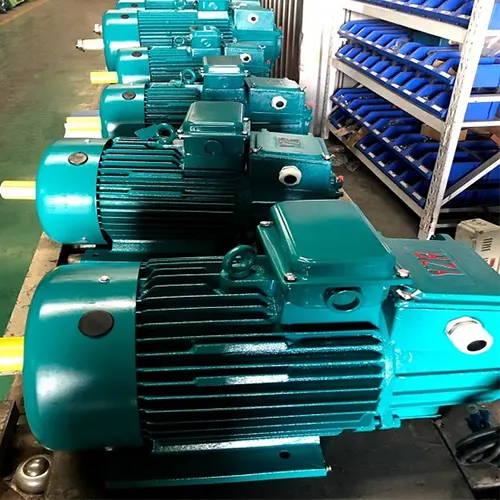
YZR / YZ Crane Motor | Specifications & Selection Guide
YZR wound-rotor and YZ squirrel-cage crane motors, including power ratings, speed classes, S2–S5 duty types, cooling, insulation, and mounting options.
| Coverage Area Type | Square / Rectangular, Linear travel / Rotation 360, 180, 120 degree |
| Application | Material handling, lifting, positioning, assembly, maintenance, loading/unloading, |
| Certifications | CE / ISO / SGS / Other third-party inspection |
| Customization | Customized material handling cranes solutions available for indoor, outdoor, hazardous, corrosive, c |
Crane Manufacturer: Yuantai Cranes – 30+ Years Professional Crane Manufacturer from China
Category: Crane Kit Parts
Tags:
Your Trusted Overhead Crane Manufacturer & Supplier
YZR / YZ Crane Motors — Full Specifications, Duty Types & Smart Selection Guide
Wound-Rotor & Squirrel-Cage Motors Explained: Power Ratings, Speed Classes, S2–S5 Duty, Cooling & Mounting Options
YZR / YZ Crane Motor for Overhead Cranes & Metallurgical Applications
YZR and YZ series crane motors are three-phase induction motors designed for crane, metallurgical, and similar industrial machinery. They are intended for operating conditions involving frequent starting, braking, intermittent operation, vibration, and mechanical shock.
The YZR series uses a wound rotor, while the YZ series uses a squirrel-cage rotor. Motor selection depends on the required power, speed, duty cycle, starting frequency, braking conditions, electrical supply, and installation requirements.
Yuantai Crane supplies crane motor solutions for overhead cranes, EOT cranes, gantry cranes, metallurgical cranes, and other industrial lifting equipment. Our engineering team can evaluate the required motor configuration using your existing motor model, nameplate, crane mechanism specifications, or technical drawings.
Key Product Features
- YZR wound-rotor and YZ squirrel-cage motor series
- Three-phase electrical supply, with 380 V and 50 Hz specified in the catalog
- Multiple frame sizes and speed classes
- S2 short-time and S3 intermittent periodic duty ratings
- Technical data covering specified S4 and S5 operating conditions
- F-class and H-class insulation options
- IP44 and IP54 protection configurations
- Multiple cooling and mounting arrangements
Contact Us to Request YZR / YZ Crane Motor Selection
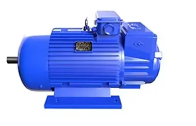
Single - shaft output Note: All frames above 180 are conical shafts
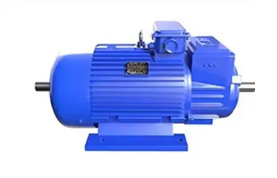
Dual-axis Output Note: All frames above 180 are conical shafts
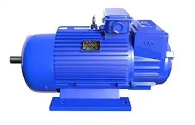
Single - shaft output Note:112-160 frame sizes are all straight shafts
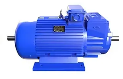
Dual-axis Output Note:112-160 frame sizes are all straight shafts
YZR / YZ Crane Motor — General Specifications
Parameter |
Specification |
|---|---|
Product Series |
YZR / YZ Crane & Metallurgical Motors |
Motor Type |
Three-phase induction motor |
Rotor Type |
YZR: Wound rotor; YZ: Squirrel-cage rotor |
Frame Size |
112–400, depending on series and configuration |
Rated Voltage |
380 V |
Frequency |
50 Hz |
Phase |
3 Phase |
Speed Classes |
600 / 750 / 1000 r/min |
Basic Duty |
S3-40% |
Other Duty Ratings |
S2-30 min / 60 min; S3-15% / 25% / 60% / 100%; specified S4 / S5 conditions |
Insulation Class |
F / H |
Protection Grade |
IP44 / IP54 |
Cooling Methods |
IC0041 / IC0141 / IC0151 |
Installation |
IM1001 / IM1002 / IM1003 / IM1004 / IM3001 / IM3003 / IM3011 / IM3013 |
Standard Installation Altitude |
Up to 1,000 m under catalog conditions |
Ambient Temperature |
Up to 40°C under standard conditions; up to 60°C for specified metallurgical configurations |
Application |
Overhead cranes, gantry cranes, metallurgical cranes, and similar industrial machinery |
YZR vs. YZ Crane Motor
YZR and YZ motors are designed for crane and metallurgical applications. The main difference is their rotor construction, which affects motor selection and the requirements of the crane drive system. Understanding these differences helps buyers identify the appropriate motor series for their equipment.
- YZR series: Wound-rotor three-phase induction motor for metallurgical and crane applications, conforming to JB/T10105-1999.
- YZ series: Squirrel-cage three-phase induction motor for metallurgical and crane applications, conforming to JB/T10104-1999.
- Power output range and mounting dimensions comply with IEC72. The relation between power output and mounting dimensions is similar to JEM1202 (Japan) and DIN42681 (Germany); most are interchangeable.
- Rated voltage: 380 V; rated frequency: 50 Hz.
- Suitable for operation at altitudes up to 1,000 m.
- Insulation classes: Class F for ambient temperature up to 40 °C (general applications); Class H for ambient temperature up to 60 °C (metallurgical applications). Both classes share the same technical data.
- Protection: IP44 for general applications; IP54 for metallurgical applications.
- Good enclosure sealing.
| Parameter | YZR Crane Motor | YZ Crane Motor |
|---|---|---|
| Rotor type | Wound rotor | Squirrel-cage rotor |
| Motor category | Three-phase crane and metallurgical induction motor | Three-phase crane and metallurgical induction motor |
| Main selection considerations | Power, speed, rotor characteristics, duty cycle, and starting requirements | Power, speed, duty cycle, and starting requirements |
| Technical information required | Model, rated power, speed, voltage, rotor data where applicable, and duty | Model, rated power, speed, voltage, and duty |
The appropriate motor series depends on the crane mechanism, operating cycle, and electrical requirements. Before selecting a replacement motor or specifying a new one, confirm the existing motor model, rated power, speed, supply voltage, and duty rating. For YZR motors, also check the rotor specifications and starting requirements to ensure compatibility with the crane's control system.
YZR / YZ Crane Motor Model Designation
The YZR series is a wound-rotor three-phase induction motor designed for crane and metallurgical applications. The model designation encodes frame size, frame length and pole number.
Example: YZR 132M1-6
The catalog illustrates the model designation using YZR 132M1-6.
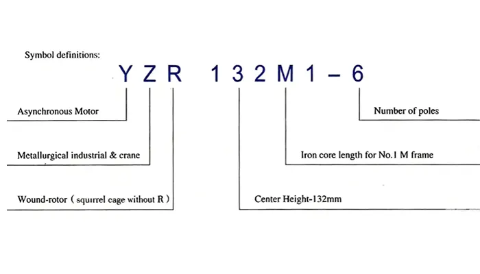
Model Designation Example: YZR132M1-6
- YZR: Wound-rotor crane and metallurgical motor series
- 132: 132 mm center height / frame size designation
- M1: Frame length designation
- 6: Number of poles
Each part of the model code tells you the motor's frame size, mounting length and speed characteristics — making it easy to match the motor to your crane duty and operating conditions.
Use the complete motor designation when requesting a quotation or identifying a replacement motor. The model alone may not establish every requirement, particularly when the existing motor has a special shaft, mounting arrangement, electrical configuration, or duty rating.
3. Frame Sizes, Power Ratings & Speed Classes
The catalog presents the relationship between motor frame size, synchronous speed class, and rated power. It also provides detailed performance tables for different operating duties.
Frame Size vs. Synchronous Speed and Power
| Frame Size | 1000 r/min | 750 r/min | 600 r/min |
|---|---|---|---|
| 112M | 1.5 kW | — | — |
| 132M1/M2 | 2.2 / 3.7 kW | — | — |
| 160M/L | 5.5 / 7.5 kW | — | — |
| 180L | 11 kW | 7.5 kW | — |
| 200L | 15 kW | 11 kW | — |
| 225M | 22 kW | 15 kW | — |
| 250M | 30 kW | 22 kW | — |
| 280S/M | 45 / 37 kW | 37 / 30 kW | — |
| 315S/M | 75 / 55 kW | 55 / 45 kW | — |
| 355L1/L2 | — | 90 / 75 kW | — |
| 400L1/L2 | — | — | 160 / 200 kW |
Frame Size Range
The catalog covers frame sizes from 112 to 400, with available combinations depending on the motor series and configuration.
Speed Classes
| Speed class | Catalog designation |
|---|---|
| Higher speed class | 1000 r/min |
| Intermediate speed class | 750 r/min |
| Lower speed class | 600 r/min |
These are the catalog's speed classes. The actual rated operating speed shown in the detailed performance tables can differ from the synchronous speed designation.
How to Read the Power Ratings
Motor output must be checked against the correct combination of:
- Frame size and model
- Speed class
- S2 or S3 duty rating
- S3 duty-cycle percentage
- Electrical and mechanical requirements
The catalog's frame-size table and detailed performance tables serve different purposes. Use the frame-size table for an initial model comparison, then confirm the applicable power, current, speed, rotor voltage, inertia, and weight in the detailed table for the selected model and duty.
Crane Motor Duty Types: S2, S3, S4 & S5
Duty classification is a central consideration when selecting a crane motor. A motor's rated power cannot be evaluated independently of its operating cycle. The basic duty is S3-40%.
S2 Short-time Duty
Operation under constant load for a fixed time, then rest and de-energized before thermal equilibrium is reached.
S3 Intermittent Periodic Duty
A series of identical cycles, each consisting of a constant-load running period and a rest/de-energized period.
S4 Intermittent Periodic Duty with Starting
Each cycle consists of a starting period, a constant-load running period, and a rest/de-energized period.
S5 Intermittent Periodic Duty with Starting and Electric Braking
Each cycle consists of a starting period, a constant-load running period, a fast electric braking period, and a rest/de-energized period.
Equivalent Starting Conversion
Four inching operations (final speed not exceeding 25% of rated speed) equal one start.
One electric braking operation (braking to 1/3 of rated speed) equals 0.8 start.
When selecting a motor, all starting and braking conditions must be converted into equivalent starts per hour based on equivalent heating to determine the motor rating.
Equivalent Starting Number & Operating Cycle
| Duty type | Equivalent starts/h | No. of starts/h | No. of touch starts/h | No. of brakes/h | No. of brakes & reverses/h |
|---|---|---|---|---|---|
| S3 | 6 | 6 | 0 | 0 | 0 |
| S3 | 4 | 0 | 8 | 0 | 0 |
| S3 | 2 | 0 | 8 | 2 | 0 |
| S4 | 150 | 150 | 0 | 0 | 0 |
| S4 | 100 | 0 | 200 | 0 | 0 |
| S5 | 80 | 0 | 0 | 80 | 0 |
| S5 | 65 | 0 | 130 | 65 | 0 |
| S5 | 30 | 0 | 160 | 30 | 30 |
| S4 | 300 | 300 | 0 | 0 | 0 |
| S4 | 200 | 0 | 400 | 0 | 0 |
| S5 | 160 | 0 | 0 | 160 | 0 |
| S5 | 130 | 0 | 260 | 130 | 0 |
| S5 | 60 | 0 | 320 | 60 | 60 |
| S4 | 600 | 600 | 0 | 0 | 0 |
| S4 | 400 | 0 | 800 | 0 | 0 |
| S5 | 320 | 0 | 0 | 320 | 0 |
| S5 | 260 | 0 | 520 | 260 | 0 |
| S5 | 120 | 0 | 640 | 120 | 120 |
Operating Conditions to Identify
Crane motors can experience repeated starts, inching movements, reversals, and braking operations. These conditions influence motor heating and must be considered alongside rated power. When selecting a motor, identify:
- Normal starts per hour
- Touch starts or inching operations
- Reversing frequency
- Braking frequency
- Operating and rest periods
- Applicable S4 or S5 duty conditions
The catalog includes an equivalent-starting-number table with specified combinations of starting, touch starting, reversing, and braking.
Engineering Note
Do not use a single starts-per-hour value as a substitute for the complete duty cycle. Provide the actual operating pattern so the selected motor can be checked against the appropriate catalog conditions.
Electrical Specifications
| Parameter | Catalog specification |
|---|---|
| Motor series | YZR / YZ |
| Motor type | Crane and metallurgical three-phase induction motor |
| Rotor | Wound rotor for YZR; squirrel cage for YZ |
| Rated voltage | 380 V |
| Frequency | 50 Hz |
| Phase | Three-phase |
| Basic duty | S3-40% |
| Speed classes | 600 / 750 / 1000 r/min |
| Frame size range | 112–400 |
| Insulation | F / H |
| Protection | IP44 / IP54 |
Voltage, frequency, power, speed, rotor configuration, and duty rating must be checked against the motor's actual nameplate and the requirements of the crane electrical system. Confirm any non-standard supply requirements before ordering.
Insulation, Protection & Environmental Conditions
Insulation Class
The catalog identifies F-class and H-class insulation configurations.
- Class F: The catalog specifies a standard ambient temperature not exceeding 40°C.
- Class H: The catalog identifies configurations for metallurgical applications with ambient temperatures up to 60°C.
The applicable motor configuration and temperature limit should be confirmed for the intended installation.
Protection Grade
The catalog lists IP44 and IP54 protection configurations.
The appropriate grade depends on the specified motor configuration and operating environment. Confirm whether additional protection is required for dust, moisture, heat, or other site conditions.
Installation Altitude
The catalog specifies an installation altitude of up to 1,000 m under its stated conditions. Installations outside those conditions require technical confirmation.
Cooling Methods
The catalog identifies three cooling codes across its motor configurations.
| Cooling code | Catalog description |
|---|---|
| IC0041 | External natural cooling |
| IC0141 | Fan cooling |
| IC0151 | Fan cooling with internal circulation |
The catalog associates IC0041 primarily with smaller frame motors, IC0141 with larger frame motors, and IC0151 with a specified 400-frame configuration.
Check the cooling code for the exact motor model before specifying a replacement. Do not assume that all frame sizes use the same cooling arrangement.
Motor Construction & Main Components
The catalog includes construction and component information relevant to motor identification, installation, and maintenance. The following sections cover the stator and rotor, slip rings and brushes, bearings, and the construction schemes of the YZ and YZR crane motors.
Stator and Rotor
The motor's stator and rotor form the main electromagnetic assembly. The rotor construction differs between the YZR wound-rotor series and the YZ squirrel-cage series.
Slip Rings and Brushes
Slip-ring and brush information is relevant to YZR wound-rotor motors. The catalog provides component dimensions by frame size.
When replacing brushes or related components, confirm the motor frame and the dimensions in the applicable table.
Bearings
The catalog lists bearing arrangements by motor frame, including load-end and non-load-end bearing designations.
Use the original model and the applicable bearing table when identifying replacement components. Bearing designations should be confirmed against the exact motor configuration.
Construction Scheme of YZ 160-250 Motor
Fig.4 shows the main construction components of the YZ 160-250 crane motor. Each numbered part is identified below.
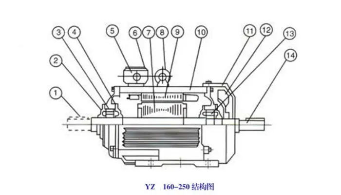
Main Components (1–14)
- 1. Shaft end key — transmits torque from the motor shaft to the driven equipment
- 2. Outer bearing cover — protects and secures the outer side of the bearing
- 3. End cover — closes the motor end and supports the bearing assembly
- 4. Inner bearing cover — secures the inner side of the bearing
- 5. Terminal box frame — holds the terminal box and electrical connections
- 6. Terminal box cover — protects the terminal connections
- 7. Rotor — the rotating part of the motor
- 8. Eyebolt — lifting point for motor handling and installation
- 9. Stator — the stationary electromagnetic part of the motor
- 10. Frame — the main motor housing and structural body
- 11. Fan cover — protects the cooling fan
- 12. Cooling fan — provides forced air cooling during operation
- 13. Bearing — supports the rotating shaft
- 14. Shaft — transmits mechanical power to the load
Construction Scheme of YZR 160-250 Motor
Fig.5 shows the main construction components of the YZR 160-250 wound-rotor crane motor. The 23 numbered parts are grouped below by function — from external protection and electrical connections to the core electromagnetic parts, cooling system and shaft output.
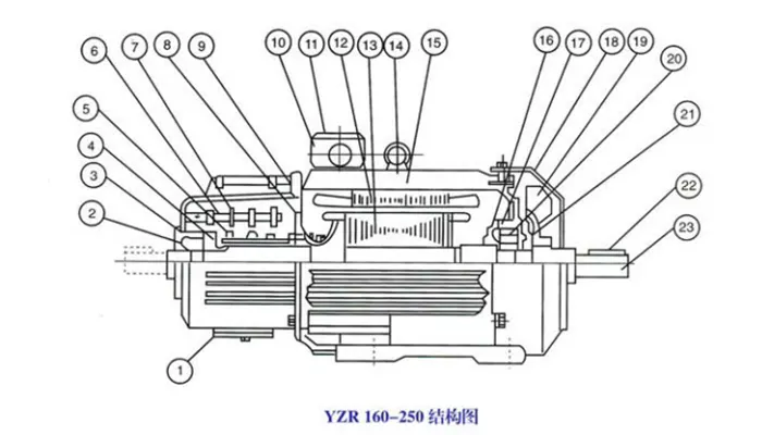
A. Housing & Protection
- 1. Dust-vent cover — covers the ventilation openings and keeps dust out
- 2. Outer bearing cover (non-drive end) — protects the outer side of the bearing
- 3. Front end cover — closes the front end of the motor housing
- 4. Inner bearing cover (non-drive end) — secures the inner side of the bearing
- 5. Dust shield (divider shield) — separates the slip-ring chamber from the main motor body
B. Electrical Connections
- 6. Slip ring — transfers electrical power to the wound rotor
- 7. Brush holder mounting rod — supports and positions the brush holders
- 8. Brush holder — holds the carbon brushes against the slip ring
- 9. Inspection cover — allows access to the slip ring and brush assembly
- 10. Terminal box frame — holds the terminal box and electrical connections
- 11. Terminal box cover — protects the terminal connections
C. Core Electromagnetic Parts
- 12. Stator — the stationary electromagnetic part of the motor
- 13. Rotor — the rotating wound-rotor part of the motor
- 14. Eyebolt — lifting point for motor handling and installation
- 15. Frame — the main motor housing and structural body
D. Cooling & Bearings
- 16. Inner bearing cover (drive end) — secures the inner side of the drive-end bearing
- 17. End cover (drive end) — closes the drive end of the motor
- 18. Fan cover — protects the cooling fan
- 19. Cooling fan — provides forced air cooling during operation
- 20. Bearing (drive end) — supports the rotating shaft at the drive end
E. Shaft & Output End
- 21. Outer bearing cover (drive end) — protects the outer side of the drive-end bearing
- 22. Shaft end key — transmits torque from the motor shaft to the driven equipment
- 23. Shaft — transmits mechanical power to the load
Construction Scheme of YZR 280-355 Motor
Fig.6 shows the main construction components of the YZR 280-355 wound-rotor crane motor. The 25 numbered parts are grouped below by function — including the rotor bearer and rotor clamper used on this larger frame size.
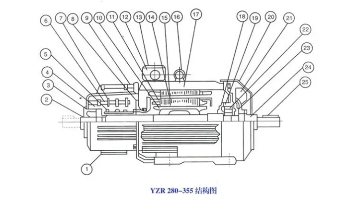
A. Housing & Protection
- 1. Dust-vent cover — covers the ventilation openings and keeps dust out
- 2. Outer bearing cover (non-drive end) — protects the outer side of the non-drive-end bearing
- 3. Front end cover — closes the front end of the motor housing
- 4. Inner bearing cover (non-drive end) — secures the inner side of the non-drive-end bearing
- 5. Dust shield (divider shield) — separates the slip-ring chamber from the main motor body
B. Electrical Connections
- 6. Slip ring — transfers electrical power to the wound rotor
- 7. Brush holder mounting rod — supports and positions the brush holders
- 8. Brush holder — holds the carbon brushes against the slip ring
- 9. Inspection cover — allows access to the slip ring and brush assembly
C. Rotor Support & Clamping
- 10. Bearer for rotor — supports the rotor assembly in this larger frame size
- 11. Rotor clamper — locks the rotor in position during transport or maintenance
D. Terminal Box
- 12. Terminal box frame — holds the terminal box and electrical connections
- 13. Terminal box cover — protects the terminal connections
E. Core Electromagnetic Parts
- 14. Stator — the stationary electromagnetic part of the motor
- 15. Rotor — the rotating wound-rotor part of the motor
- 16. Eyebolt — lifting point for motor handling and installation
- 17. Frame — the main motor housing and structural body
F. Cooling & Bearings
- 18. Inner bearing cover (drive end) — secures the inner side of the drive-end bearing
- 19. End cover (drive end) — closes the drive end of the motor
- 20. Fan cover — protects the cooling fan
- 21. Cooling fan — provides forced air cooling during operation
- 22. Bearing (drive end) — supports the rotating shaft at the drive end
G. Shaft & Output End
- 23. Outer bearing cover (drive end) — protects the outer side of the drive-end bearing
- 24. Shaft — transmits mechanical power to the load
- 25. Shaft end key — transmits torque from the motor shaft to the driven equipment
Mounting Arrangements
The catalog includes installation designations IM1001, IM1002, IM1003, IM1004, IM3001, IM3003, IM3011, and IM3013. The applicable arrangement depends on the motor frame and configuration. Before ordering, confirm the items below.
Installation Designations
The catalog includes the following installation designations:
IM1001, IM1002, IM1003, IM1004, IM3001, IM3003, IM3011, and IM3013.
The applicable arrangement depends on the motor frame and configuration.
Before ordering, confirm:
- Mounting designation
- Installation orientation
- Frame size
- Shaft extension and dimensions
- Coupling or transmission interface
- Available installation space
The catalog also states that the shaft extension can be made according to customer requirements. Any customized shaft should be confirmed against the required dimensions and mechanical interface.
YZR 112–400 IM1 Mounting and Overall Dimensions (Table 10)
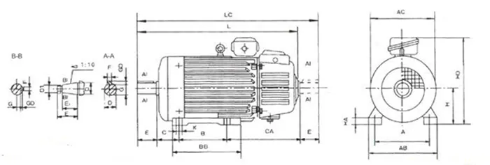
Table provides dimensions for frame sizes 112M–400L, including center height H, A, B, C, CA, K, D, E, F, G, GD, and overall dimensions AB, AC, HD, BB, L, LC, HA.
| Frame Size | H | A | B | C | K | D | E | F | G | GD | AB | AC | HD | BB | L | LC | HA |
|---|---|---|---|---|---|---|---|---|---|---|---|---|---|---|---|---|---|
| 112M | 112 | 190 | 140 | 70 | 12 | 32 | 80 | 10 | 27 | — | 250 | 245 | 330 | 235 | 500 | 670 | 15 |
| 132M | 132 | 216 | 178 | 89 | 12 | 38 | 80 | 10 | 33 | — | 275 | 265 | 360 | 260 | 645 | 727 | 17 |
| 160M | 160 | 254 | 210 | 108 | 15 | 48 | 110 | 14 | 42.5 | 82 | 320 | 325 | 420 | 290 | 758 | 868 | 20 |
| 160L | 160 | 254 | 254 | 108 | 15 | 48 | 110 | 14 | 42.5 | 82 | 320 | 325 | 420 | 335 | 800 | 912 | 20 |
| 180L | 180 | 279 | 279 | 121 | 15 | 55 | 140 | 16 | 49.9 | 105 | 360 | 360 | 460 | 380 | 875 | 980 | 22 |
| 200L | 200 | 318 | 305 | 133 | 19 | 60 | 140 | 16 | 49.9 | 105 | 405 | 405 | 510 | 400 | 970 | 1118 | 25 |
| 225M | 225 | 356 | 311 | 149 | 19 | 65 | 140 | 18 | 51.4 | 130 | 455 | 450 | 545 | 410 | 1050 | 1190 | 28 |
| 250M | 250 | 406 | 349 | 168 | 24 | 70 | 170 | 20 | 51.4 | 130 | 515 | 480 | 605 | 510 | 1195 | 1317 | 30 |
| 280S | 280 | 457 | 368 | 190 | 24 | 85 | 170 | 22 | 55.4 | — | 575 | 535 | 665 | 530 | 1275 | 1458 | 32 |
| 280M | 280 | 457 | 419 | 190 | 24 | 85 | 170 | 22 | 55.4 | — | 575 | 535 | 665 | 580 | 1315 | 1489 | 32 |
| 315S | 315 | 508 | 406 | 216 | 28 | 95 | 210 | 25 | 62.4 | 165 | 640 | 610 | 750 | 630 | 1440 | 1613 | 35 |
| 315M | 315 | 508 | 457 | 216 | 28 | 95 | 210 | 25 | 62.4 | 165 | 640 | 610 | 750 | 730 | 1540 | 1804 | 38 |
| 355M | 355 | 610 | 560 | 254 | 35 | 110 | 250 | 28 | 69.4 | 200 | 740 | 710 | 840 | 800 | 1650 | 1934 | 40 |
| 355L | 355 | 610 | 630 | 254 | 35 | 110 | 250 | 28 | 69.4 | 200 | 740 | 710 | 840 | 900 | 1720 | 2120 | 42 |
| 400L | 400 | 686 | 710 | 280 | 35 | 130 | 290 | 32 | 69.4 | 200 | 855 | 840 | 950 | 910 | 1865 | — | 45 |
All dimensions in mm. Refer to the complete Table 10 for full details.
YZR 112–315 IM3 Mounting and Overall Dimensions
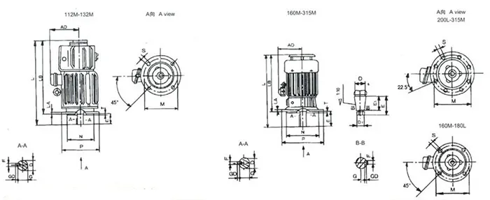
Table provides IM3 flange mounting dimensions for frame sizes 112M–315M, including flange code (F215, F265, F300, F400, F500, F600), M, N, P, R, S, T, LA, and overall dimensions AD, L, LB, HD.
| Frame Size | Flange Code | M | N | P | R | S | T | LA | AD | L | LB | HD |
|---|---|---|---|---|---|---|---|---|---|---|---|---|
| 112M | F215 | 215 | 180 | 250 | — | 15 | 4 | 14 | 230 | 595 | 515 | 330 |
| 132M | F265 | 265 | 230 | 300 | — | 15 | 4 | 18 | 250 | 645 | 565 | 360 |
| 160M | F300 | 300 | 250 | 350 | — | 19 | 5 | 20 | 280 | 828 | 718 | 420 |
| 160L | F300 | 300 | 250 | 350 | — | 19 | 5 | 20 | 310 | 872 | 762 | 460 |
| 180L | F400 | 400 | 350 | 450 | — | 19 | 5 | 22 | 330 | 915 | 805 | 510 |
| 200L | F400 | 400 | 350 | 450 | — | 19 | 5 | 22 | 350 | 1060 | 910 | 545 |
| 225M | F500 | 500 | 450 | 550 | — | 24 | 6 | 25 | 385 | 1110 | 970 | 605 |
| 250M | F500 | 500 | 450 | 550 | — | 24 | 6 | 25 | 420 | 1260 | 1126 | 665 |
| 280S | F600 | 600 | 550 | 660 | — | 24 | 6 | 25 | 435 | 1370 | 1200 | 750 |
| 280M | F600 | 600 | 550 | 660 | — | 24 | 6 | 25 | 435 | 1420 | 1250 | 750 |
| 315S | F600 | 600 | 550 | 660 | — | 24 | 6 | 25 | 435 | 1475 | 1305 | 840 |
| 315M | F600 | 600 | 550 | 660 | — | 24 | 6 | 25 | 435 | 1525 | 1355 | 840 |
All dimensions in mm. Refer to the complete Table 11 for A, B, C, D, E, F, G, GD, K and other details.
YZR / YZ Crane Motor Applications
YZR and YZ motors are intended for crane, metallurgical, and similar industrial machinery.
Typical application categories include:
- Overhead cranes and EOT cranes
- Gantry cranes and goliath cranes
- Metallurgical cranes
- Industrial lifting equipment
- Crane mechanisms involving frequent starting and braking
- Equipment operating under specified vibration and shock conditions
The correct motor depends on the mechanism, operating cycle, load characteristics, electrical supply, and installation conditions. Confirm the suitability of the selected motor for the intended hoisting or traveling mechanism.
How to Select the Right Crane Motor
A reliable selection process starts with the actual operating requirements, not only the motor's nominal power. The following steps outline the information needed to select a suitable crane motor.
Identify the Crane and Mechanism
Specify the crane type and whether the motor is used for hoisting, trolley travel, crane travel, or another mechanism.
Confirm the Motor Series
Identify whether the requirement is for a YZR wound-rotor motor or a YZ squirrel-cage motor.
Confirm Power and Speed
Provide the required power, operating speed, existing motor model, or original nameplate data.
Specify the Duty Cycle
Confirm whether the application requires S2, S3, S4, or S5 duty. For S3, specify the required duty percentage.
Confirm Starting and Braking Conditions
Provide starts per hour, inching frequency, reversing frequency, braking frequency, and the actual operating cycle where available.
Check the Environment
Confirm ambient temperature, installation altitude, protection requirements, and any special metallurgical operating conditions.
Confirm Electrical and Mechanical Interfaces
Specify voltage, frequency, phase, mounting arrangement, shaft dimensions, and available installation space.
Verify the Detailed Catalog Rating
Check the selected model's power, current, speed, rotor voltage where applicable, inertia, weight, and duty rating in the corresponding technical table.
YZR / YZ Crane Motor Replacement
Replacing an existing crane motor requires more than matching its power rating. Differences in frame size, speed, duty, electrical configuration, or shaft dimensions can prevent direct replacement.
Yuantai Crane can evaluate a replacement requirement using the following information:
- Existing motor model and nameplate photograph
- Motor series and rotor type
- Rated power and speed
- Voltage, frequency, and phase
- Duty type and operating cycle
- Rotor voltage where applicable
- Frame size and mounting arrangement
- Shaft extension and coupling dimensions
- Installation environment
CTA: Send Your Existing Motor Nameplate for Replacement Evaluation
YZR / YZ Crane Motor Specifications Summary
| Parameter | Specification |
|---|---|
| Product | YZR / YZ Crane Motor |
| Motor category | Crane and metallurgical three-phase induction motor |
| Rotor configuration | Wound rotor / squirrel cage |
| Frame sizes | 112–400 |
| Rated supply in catalog | 380 V, 50 Hz, three-phase |
| Speed classes | 600 / 750 / 1000 r/min |
| Duty types | S2 / S3, with specified S4 and S5 operating conditions |
| Basic duty | S3-40% |
| Insulation | F / H |
| Protection grade | IP44 / IP54 |
| Cooling codes | IC0041 / IC0141 / IC0151 |
| Mounting codes | IM1001 / IM1002 / IM1003 / IM1004 / IM3001 / IM3003 / IM3011 / IM3013 |
| Installation altitude | Up to 1,000 m under catalog conditions |
| Ambient temperature | Up to 40°C standard; up to 60°C for specified metallurgical configurations |
| Customization | Shaft extension according to customer requirements |
| Manufacturer | Yuantai Crane(s) – China manufacturer |
Note: The exact rated power, current, speed, rotor voltage, inertia, weight, and dimensional data must be confirmed in the detailed catalog table for the selected model and duty condition.
FAQs About YZR / YZ Crane Motors
YZR wound-rotor and YZ squirrel-cage motors are widely used in crane and metallurgical applications. The following questions and answers cover motor series, duty ratings, cooling methods, replacement considerations, and quotation requirements.
What is a YZR crane motor?
A YZR crane motor is a wound-rotor three-phase induction motor designed for crane, metallurgical, and similar industrial machinery.
What is the difference between YZR and YZ motors?
The YZR series uses a wound rotor, while the YZ series uses a squirrel-cage rotor. Selection depends on the crane mechanism and the required electrical and operating characteristics.
What does YZR 132M1-6 mean?
In the catalog's example, YZR identifies the motor series, 132 indicates the center-height/frame designation, M1 indicates the frame-length designation, and 6 indicates the number of poles.
What is the basic duty of a YZR / YZ crane motor?
The catalog identifies S3-40% as the basic motor duty. It also provides other S2 and S3 ratings and specified S4/S5 operating conditions.
What does S3-40% mean?
It identifies an intermittent periodic duty in which operation accounts for 40% of the specified duty cycle. The applicable rating must be taken from the corresponding motor data table.
Are YZR motors suitable for metallurgical applications?
The catalog covers crane and metallurgical motor applications and identifies configurations with H-class insulation and protection grades intended for specified operating conditions. Confirm the actual temperature and environmental requirements before selection.
What cooling methods are available?
The catalog lists IC0041 external natural cooling, IC0141 fan cooling, and IC0151 fan cooling with internal circulation for specified configurations.
Can a YZR / YZ motor replace an existing crane motor?
Potentially, subject to engineering verification. The replacement must match the required power, speed, duty, electrical supply, mounting arrangement, shaft dimensions, and other relevant parameters.
What information is needed for a motor quotation?
Provide the existing motor model or nameplate, crane mechanism, required power and speed, voltage, frequency, duty cycle, starting and braking conditions, mounting dimensions, and operating environment.
Request YZR / YZ Crane Motor Selection & Quotation
Need a crane motor for a new project or an existing crane? Send your motor model, nameplate, technical drawing, or operating requirements to Yuantai Crane.
Our team can review the applicable motor series, frame size, power rating, speed class, duty type, cooling arrangement, mounting configuration, and replacement compatibility.
Ordering Information
When ordering, please specify: motor type, output power, synchronous speed, insulation class, mounting arrangement, and duty type.
Example:YZR160M1-6 5.5 kW 1000 r/min Class F IM1001 S3-40%
- If two shaft extensions are required, this must be stated in the order; otherwise, the motor is supplied with one shaft extension.
- If no duty type is specified, the nameplate will show data for the basic duty S3-40% only.
- For duty types outside S2–S5, consultation with the manufacturer is required.
- For S4 and S5 duty, the motor selection must be verified against the actual load moment of inertia.
Use this final table beside the quotation form.
- Motor Series: YZR wound-rotor or YZ squirrel-cage (e.g., YZR)
- Motor Model: Existing or required model (e.g., YZR 132M1-6)
- Rated Power: kW (e.g., 5.5 kW)
- Speed: r/min (e.g., 1,000 r/min)
- Voltage / Frequency: V / Hz (e.g., 380 V / 50 Hz)
- Duty Type: S2 / S3 / S4 / S5 (e.g., S3-40%)
- Starting and Braking: Starts per hour and braking type (e.g., frequent starts with electromagnetic braking)
- Operating Environment: Temperature, dust, and moisture (e.g., indoor steel workshop)
- Mounting and Shaft Dimensions: Installation and mechanical interface (e.g., IM1001, matching shaft and coupling)
- Reference Documents: Nameplate photo or technical drawing (e.g., existing motor nameplate)
Recommended page structure: Keep the general specification table near the top, the frame/power table in the selection section, detailed performance tables in a dedicated technical-data section, and brush, bearing, cooling, and mounting tables lower on the page. This gives buyers a quick overview without sacrificing the technical depth needed for motor selection.
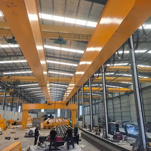

Yuantai Cranes
Overhead Crane Manufacturer with CE, ISO, SGS, CNEX Certificates.
- Main Specifications - Capacity: 0.5–550 tons | Span: up to 40m | Speed: 0.8–12 m/min | Duty: A3–A7 | Power: 380–690V, 50/60Hz | Control: pendant/remote/cabin
- Full engineering: FEA/PLC/VFD + in-house build + global delivery + on-site support, for workshops, factories, EPC contractors, industrial projects, etc.
- Support: design, manufacturing, testing, service – end-to-end, customized lifting solutions worldwide.
How to Get an Accurate Crane Price for Your Application?
Tips: Copy the spec list, fill in your details, and paste it into the form on the right/ down-below for a quick price.
- Crane type:_____ . (e.g., overhead crane, gantry crane, jib crane)
- Max weight to lift:_____ tons. (e.g., 2t, 5t, 10t, 20t, 50t)
- Lifting height:_____ m. (How high does the hook need to reach?
- Workshop width (span):_____ m . (Distance between the two crane rails)
- Travel distance:_____ m . (How long does the crane need to move along the runway?)
- Control type:_____. (Pendant / remote / cabin Control)
- Power supply:_____. (Local voltage & frequency – e.g., 380V, 50Hz, 3-phase)
- What will it be used for?_____ (e.g., steel fabrication, concrete products, mold handling, general manufacturing, etc.)
- Any special requirements?_____ (e.g., extreme temperature, dusty or explosive environment, special paint color, etc.)
Just leave a message via the contact form and our hoist and crane engineer will contact you with in 24working hours.
Get Your Custom Quote–Quick & Easy
Fill in what you know. Skip what you don't – we'll help.Any question will be reply with 24 working hours