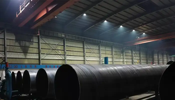
Overhead Cranes for Silo Manufacturing: Applications & Capacity
Choose the Right Overhead Crane for Silo Production — Lifting Capacities, Span Options, Duty Classes & Expert Selection Tips
Silo manufacturing involves handling large steel plates, coils, rolled cylindrical sections, hopper cones, roof structures, and completed silo assemblies. These components vary considerably in weight, dimensions, shape, and lifting requirements. An appropriately designed overhead crane system helps manufacturers move materials between production areas, position components for welding and assembly, and handle finished structures safely and efficiently.
Selecting an overhead crane for a silo manufacturing factory requires more than choosing a lifting capacity. Buyers also need to consider component dimensions, steel thickness, lifting attachments, crane span, lifting height, runway length, working duty, and workshop conditions.
This guide explains the main overhead crane applications in silo manufacturing, typical component weights, recommended crane capacity ranges, lifting equipment options, and the technical information required to select a suitable crane system.
Why Do Silo Manufacturing Factories Need Overhead Cranes?
Silo production involves multiple steel fabrication and assembly operations. From raw material storage to finished silo dispatch, heavy and oversized components must be lifted and transferred between workstations.
Overhead cranes provide lifting coverage across production areas without occupying valuable floor space. They are particularly useful for handling large cylindrical sections and positioning steel structures during fabrication.
Common overhead crane applications in silo manufacturing include:
- Raw material handling: Lifting steel plates, coils, profiles, and structural materials.
- Steel plate processing: Loading and unloading cutting, shearing, and preparation machines.
- Plate rolling: Handling rolled steel plates and cylindrical shell sections.
- Shell fabrication: Positioning cylindrical sections for welding and alignment.
- Hopper and cone fabrication: Moving conical components and supporting structures.
- Roof fabrication: Handling roof panels, beams, and structural frames.
- Final assembly: Positioning large silo components during assembly.
- Finished product handling: Moving completed sections to storage and dispatch areas.
The required crane configuration depends on the maximum suspended load, component dimensions, production frequency, building structure, and lifting method.
What Materials and Components Need to Be Lifted in Silo Manufacturing?
Before selecting an overhead crane, manufacturers should identify the materials and components handled in each production area. Their weight, dimensions, shape, and center of gravity directly affect crane capacity and lifting attachment selection.
Steel Plates and Sheet Materials
Steel plates are among the most frequently handled materials in silo manufacturing. They are used to fabricate cylindrical shells, hopper sections, roofs, stiffeners, and structural components.
Typical characteristics:
- Plate length: 2–8 m
- Plate width: 1.5–2.5 m
- Plate thickness: 6–12 mm or project-specific
- Estimated individual plate weight: 0.5–3 ton
For example, a steel plate measuring 6 m × 2 m × 10 mm weighs approximately 0.94 ton.
Suitable lifting equipment for steel plates handling :
- Plate clamps
- Vacuum lifting devices, where surface and operating conditions permit
- Horizontal plate lifting beams
- Customized multi-point lifting beams or 2 units of cranes for tandem lifting
- Check more on steel sheet lifters or contact us to get your made to order solution.
For long or thin plates, the lifting arrangement should distribute the load appropriately to limit bending and deformation. 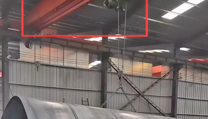
Steel Coils
Some silo manufacturing facilities use coiled steel as raw material for forming and rolling operations.
Typical characteristics:
- Coil outside diameter: 1–2 m
- Coil width: 1–1.8 m
- Estimated coil weight: 2–10 ton
The actual weight depends on the coil diameter, width, material thickness, and steel density.
Suitable lifting equipment:
- Coil C-hooks
- Coil lifting beams
- Specialized coil grabs
- Check more on our steel coil handling cranes and devices.
The lifting device should match the coil's inside diameter, outside diameter, width, and center of gravity.
Rolled Steel Plates and Cylindrical Shell Sections
After rolling, steel plates become curved sections or cylindrical shell components. These are used to manufacture the main bodies of storage silos.
Typical characteristics:
- Shell diameter: 3–12 m
- Individual shell section height: 1.5–3 m
- Plate thickness: commonly 6–12 mm in illustrative examples, but project-specific
- Estimated section weight: approximately 2–15 ton or more
The actual weight depends on diameter, height, plate thickness, reinforcements, stiffeners, and attached components.
Suitable lifting equipment:
- Spreader beams
- Multi-point lifting beams
- Customized shell lifting frames
- Double-girder overhead cranes for heavier assemblies
Large cylindrical sections require particular attention to lifting-point positions, load balance, and shell deformation.
Hopper and Cone Sections
Hopper and cone sections are used in silo discharge systems and material handling structures. Their conical geometry makes lifting and positioning more complex than handling flat plates.
Typical characteristics:
- Diameter: 2–6 m
- Estimated weight: 2–10 ton
- Dimensions and weight vary with cone angle, plate thickness, reinforcement, and design.
Suitable lifting equipment:
- Customized spreader beams
- Lifting frames
- Multi-point lifting arrangements
The lifting device should be designed around the component's geometry and approved lifting points.
Roof Panels, Structural Frames and Support Components
Silo roofs may include steel panels, beams, trusses, support frames, and connecting structures.
Typical characteristics:
- Component length: 3–12 m
- Estimated individual component weight: 1–8 ton
Suitable lifting equipment:
- Standard crane hooks
- Lifting beams
- Spreader beams
- Customized structural lifting frames
For long structural components, multiple lifting points may be required to maintain balance and prevent excessive deflection.
Completed Silo Sections and Large Assemblies
Some factories manufacture large silo sections or complete assemblies before transporting them to the installation site.
Typical characteristics:
- Component diameter: 3–12 m or larger
- Estimated weight: 5–35 ton or more
- Dimensions and weight depend on the silo design and fabrication method.
Suitable lifting equipment:
- Double-girder overhead cranes
- Engineered spreader beams
- Customized lifting frames
For exceptionally large components, the manufacturer should evaluate whether one crane or a coordinated multi-crane lifting arrangement is appropriate.
Typical Loads Handled in Silo Manufacturing
| Load Type | Illustrative Dimensions | Estimated Weight | Possible Lifting Equipment |
|---|---|---|---|
| Steel plate | 6 × 2 m × 6–12 mm | 0.57–1.13 ton | Plate clamp / lifting beam |
| Steel coil | Ø 1–2 m × 1–1.8 m width | 2–10 ton | C-hook / coil lifter |
| Rolled shell section | Ø 3–8 m × 1.5–3 m | Project-specific | Spreader beam |
| Large cylindrical shell | Ø 8–12 m × 2–3 m | Project-specific | Customized lifting frame |
| Hopper or cone | Ø 2–6 m | 2–10 ton | Spreader beam |
| Roof structure | 3–12 m long | 1–8 ton | Lifting beam |
| Structural frame | 3–12 m long | 1–8 ton | Hook / spreader beam |
| Large silo assembly | Project-specific | 5–35 ton or more | Engineered lifting arrangement |
Note: These figures are preliminary planning references rather than standardized component specifications. Actual weights must be calculated from drawings, material thickness, reinforcements, and the complete component configuration.
Where Are Overhead Cranes Used in Silo Manufacturing?
Overhead cranes are used throughout the silo manufacturing process, from raw material storage to finished product handling. Different production areas handle different steel materials and fabricated components, so crane capacity, type, and lifting equipment should match the requirements of each operation. Depending on the factory layout, some processes may share the same workshop and crane runway, while heavy fabrication and final assembly may require dedicated crane areas.
Raw Material Storage and Steel Handling
Main operations: Unloading, storing, and transferring steel plates, coils, and profiles to production areas.
Typical loads handled:
- Steel plates: approximately 0.5–3 ton.
- Steel coils: approximately 2–10 ton.
- Steel profiles and structural sections: approximately 0.5–8 ton.
Recommended crane configuration:
- Crane capacity: 5–15 ton.
- Crane type: Single-girder or double-girder overhead crane.
- Lifting equipment: Plate clamps, coil C-hooks, lifting beams, or standard hooks.
- Quantity: Typically 1–2 cranes, depending on storage area size and material handling frequency.
Steel Plate Cutting and Preparation Workshop
Main operations: Loading steel plates onto CNC plasma or laser cutting machines, unloading cut sections, and transferring prepared components to the next production stage.
Typical loads handled:
- Full-size steel plates: approximately 0.5–3 ton.
- Cut plate sections: approximately 0.2–2 ton.
- Prepared steel components: approximately 0.5–3 ton.
Recommended crane configuration:
- Crane capacity: 3–5 ton.
- Crane type: Single-girder overhead crane for many general plate-handling applications.
- Lifting equipment: Plate clamps, vacuum lifters where suitable, or horizontal lifting beams.
- Quantity: Typically 1 crane per production bay; additional cranes may be needed for separate cutting lines or larger workshops.
Plate Rolling and Cylindrical Shell Fabrication Workshop
Main operations: Feeding flat steel plates into rolling machines, removing rolled plates, handling curved sections, and transferring cylindrical shell components to welding stations.
Typical loads handled:
- Steel plates before rolling: approximately 1–5 ton.
- Rolled plate sections: approximately 1–8 ton.
- Cylindrical shell sections: approximately 2–15 ton or more, depending on diameter, height, and plate thickness.
Recommended crane configuration:
- Crane capacity: 5–20 ton.
- Crane type: Single-girder or double-girder overhead crane, depending on load weight and operating duty.
- Lifting equipment: Spreader beams, lifting beams, or customized shell lifting frames.
- Quantity: Typically 1–2 cranes per production bay, depending on the number of rolling machines and simultaneous lifting operations.
Silo Shell Welding and Assembly Workshop
Main operations: Lifting, aligning, positioning, and welding cylindrical shell sections to form the main silo body.
Typical loads handled:
- Small and medium shell sections: approximately 2–10 ton.
- Large cylindrical shell sections: approximately 5–25 ton or more.
- Reinforced shell assemblies: approximately 10–35 ton or more.
Actual weights depend on shell diameter, height, plate thickness, and additional structural components.
Recommended crane configuration:
- Crane capacity: 10–30 ton or higher for heavy assembly applications.
- Crane type: Double-girder overhead crane.
- Lifting equipment: Engineered spreader beams, multi-point lifting beams, or customized shell lifting frames.
- Quantity: Typically 1–2 cranes per assembly bay; larger workshops may require additional cranes for separate production lines.
Key features: VFD-controlled hoisting and travel, suitable lifting height, accurate positioning, and engineered lifting arrangements to maintain load balance and prevent shell deformation.
Hopper, Cone and Roof Fabrication Workshop
Main operations: Fabricating hopper sections, discharge cones, roof panels, trusses, and supporting structures before transferring them to final assembly.
Typical loads handled:
- Hopper and cone sections: approximately 2–10 ton.
- Roof panels: approximately 0.5–3 ton.
- Roof trusses and structural frames: approximately 1–8 ton.
Recommended crane configuration:
- Crane capacity: 5–15 ton.
- Crane type: Single-girder or double-girder overhead crane, depending on component weight and workshop requirements.
- Lifting equipment: Standard hooks, lifting beams, spreader beams, or customized lifting frames.
- Quantity: Typically 1 crane per fabrication bay; larger workshops may require separate cranes for hopper and roof production.
Final Assembly, Inspection and Dispatch Workshop
Main operations: Handling completed silo sections, positioning assembled structures, transferring finished components to inspection and storage areas, and preparing products for loading and transportation.
Typical loads handled:
- Completed cylindrical sections: approximately 5–25 ton.
- Large silo assemblies: approximately 10–35 ton or more.
- Finished hopper and structural assemblies: approximately 2–20 ton.
Recommended crane configuration:
- Crane capacity: 10–50 ton or higher, depending on the maximum finished component weight.
- Crane type: Double-girder overhead crane for heavy components; single-girder cranes may serve lighter handling operations.
- Lifting equipment: Standard hooks, spreader beams, or customized lifting frames.
- Quantity: Typically 1–2 cranes per assembly or dispatch bay, depending on production volume and handling requirements.
Key features: Adequate lifting height, sufficient runway coverage, VFD-controlled travel, and anti-collision protection where multiple cranes operate on the same runway.
Typical Overhead Crane Arrangements Across a Silo Manufacturing Factory
The following table summarizes the crane requirements for different production areas.
| Workshop / Production Area | Main Loads Handled | Typical Crane Capacity | Common Crane Type |
|---|---|---|---|
| Raw material storage | Steel plates, coils, profiles | 5–15 ton | Single or double girder |
| Plate cutting and preparation | Full-size plates, cut sections | 3–5 ton | Single girder |
| Plate rolling and shell fabrication | Rolled plates, cylindrical sections | 5–20 ton | Single or double girder |
| Shell welding and assembly | Large cylindrical shells, reinforced assemblies | 10–30 ton or higher | Double girder |
| Hopper and roof fabrication | Cones, roof panels, trusses | 5–15 ton | Single or double girder |
| Final assembly and dispatch | Finished silo sections, heavy structures | 10–50 ton or higher | Double girder |
Note: Capacities and crane configurations are preliminary references. Final selection depends on the maximum suspended load, lifting attachments, span, lifting height, working duty, workshop layout, and building structure.
How Many Overhead Cranes Does a Silo Manufacturing Factory Need?
The number of overhead cranes depends on the factory's production layout, material handling frequency, and the number of lifting operations that must take place simultaneously.
For example:
- Small and medium-sized factories: Raw material storage and plate preparation may share one crane runway. Plate rolling and general fabrication may also be combined into one workshop.
- Factories with dedicated production lines: Separate cranes may be installed for plate cutting, shell fabrication, and final assembly to reduce material handling delays.
- Large silo manufacturing facilities: Heavy shell assembly and finished product handling may require dedicated high-capacity double-girder cranes.
One crane may serve several workstations if its runway provides sufficient coverage and the lifting operations do not conflict. Where multiple cranes share a runway, wheel loads, operating zones, anti-collision protection, and control arrangements must be considered.
The total crane quantity should therefore be determined from the factory layout and production requirements rather than a fixed number of cranes per workshop.
Silo Manufacturing Workflow
Raw Material Storage → Steel Plate Cutting → Plate Rolling → Cylindrical Shell Fabrication → Welding and Assembly → Hopper and Roof Fabrication → Final Assembly → Inspection and Dispatch
When planning an overhead crane system, consider the complete production flow, including where materials enter, how components move between workstations, and where finished structures are stored or loaded. This helps determine the appropriate crane capacity, quantity, runway coverage, and lifting attachments for each production area.
What Is the Typical Overhead Crane Capacity for Silo Manufacturing?
The required overhead crane capacity varies according to the maximum component weight, lifting attachment, and production process. The following sections provide preliminary capacity ranges for common silo manufacturing operations and guidance on choosing between different crane capacities.
Typical Crane Capacity by Manufacturing Application
The following table provides preliminary capacity ranges for common silo manufacturing operations.
| Manufacturing Operation | Typical Load Weight | Suggested Crane Capacity |
|---|---|---|
| Steel plate storage | 0.5–3 ton | 3–5 ton |
| Steel coil handling | 2–10 ton | 5–15 ton |
| Plate cutting | 0.5–3 ton | 3–5 ton |
| Plate rolling | 1–8 ton | 5–10 ton |
| Shell fabrication | 3–15 ton | 5–20 ton |
| Shell assembly | 5–25 ton | 10–30 ton |
| Roof fabrication | 1–8 ton | 3–10 ton |
| Cone manufacturing | 2–10 ton | 5–15 ton |
| Heavy structural assembly | 10–35 ton | 15–50 ton |
| Finished silo component handling | 5–25 ton | 10–30 ton |
These are indicative ranges for preliminary equipment planning. They are not automatic capacity selections. A final crane rating must be established from the complete suspended load and applicable engineering requirements.
3–5 Ton Overhead Cranes
Suitable for:
- Small and medium-sized steel plates
- Plate cutting and preparation operations
- Light structural components
- General workshop material handling
Typical application case:
A plate preparation workshop handles steel plates measuring 6 m × 2 m × 10 mm. Each plate weighs approximately 942 kg. A 3–5 ton overhead crane can provide sufficient capacity for handling these plates, provided the lifting attachment and operating conditions are properly considered.
Recommendation:
A single-girder overhead crane is often suitable for this type of application. Plate clamps, vacuum lifters, or lifting beams can be selected according to the plate dimensions, surface condition, and handling method. For frequent plate handling, consider VFD-controlled travel to improve positioning accuracy.
5–10 Ton Overhead Cranes
Suitable for:
- Medium-sized steel coils
- Rolled steel plates
- Small cylindrical shell sections
- General fabrication and welding operations
Typical application case:
A silo factory rolls 6–8 mm thick steel plates into cylindrical shell sections for medium-sized silos. Individual sections weigh approximately 3–6 ton and need to be transferred between rolling machines and welding stations.
Recommendation:
A single-girder or double-girder overhead crane may be selected depending on the span, lifting height, working duty, and workshop structure. A spreader beam or customized shell lifting frame can help distribute the load and reduce the risk of deformation during handling.
10–20 Ton Overhead Cranes
Suitable for:
- Medium and large cylindrical shell sections
- Hopper and cone assemblies
- Heavy steel fabrication
- Shell positioning and assembly
Typical application case:
A shell fabrication workshop handles cylindrical sections with a diameter of 6–10 m. Depending on the plate thickness, section height, and reinforcements, individual sections may weigh approximately 8–15 ton.
Recommendation:
A double-girder overhead crane is worth considering for heavier components, larger spans, or demanding production duties. The lifting system should be designed around the shell geometry, center of gravity, and lifting points. VFD-controlled hoisting and travel can support smoother lifting and more accurate positioning during assembly.
20–30 Ton Overhead Cranes
Suitable for:
- Large silo shell sections
- Heavy fabricated structures
- Large hopper assemblies
- More demanding material handling operations
Typical application case:
A large silo manufacturing workshop assembles reinforced cylindrical shell sections weighing approximately 18–25 ton. The sections must be lifted, rotated or repositioned where required, and aligned for welding.
Recommendation:
A double-girder overhead crane is generally a suitable starting configuration for this load range. For long or large-diameter shell sections, use an engineered multi-point lifting beam or customized lifting frame. Check the lifting points, load distribution, headroom, and available installation space before finalizing the crane design.
30–50 Ton or Higher Overhead Cranes
Suitable for:
- Heavy silo structures
- Large industrial storage tank components
- Heavy-duty fabrication and assembly
- Oversized components requiring engineered lifting arrangements
Typical application case:
A heavy fabrication workshop manufactures large industrial storage tanks or silo sections. A completed assembly may weigh 35–45 ton and require lifting between fabrication, inspection, and dispatch areas.
Recommendation:
A heavy-duty double-girder overhead crane is commonly considered for this application. Depending on the component dimensions and lifting requirements, the system may use a customized spreader beam, multi-point lifting arrangement, or two-crane synchronized lifting system. Tandem lifting requires coordinated controls and an engineered lifting plan; the combined crane capacities alone do not establish that a lift is safe.
Quick Capacity Selection Reference
| Crane Capacity | Typical Silo Manufacturing Applications | Common Crane Configuration |
|---|---|---|
| 3–5 ton | Plate cutting, light fabrication, small components | Single girder |
| 5–10 ton | Plate rolling, small shell sections, general fabrication | Single or double girder |
| 10–20 ton | Medium shell sections, hopper assemblies, shell positioning | Usually double girder for demanding applications |
| 20–30 ton | Large shell sections, heavy structures, large hopper assemblies | Double girder |
| 30–50 ton or higher | Heavy silo structures, large tank components, final assembly | Heavy-duty double girder |
Important Factors Before Finalizing Crane Capacity
Crane capacity should not be selected based on the weight of the steel component alone. Buyers should also consider:
- Maximum lifted load: Include the workpiece, lifting beam, clamps, spreader, and other suspended accessories.
- Component dimensions: Large-diameter shells and long plates may require special lifting arrangements even when their weight is relatively low.
- Lifting method: Single-point, two-point, and multi-point lifting arrangements affect load distribution and crane selection.
- Lifting height and headroom: Check the required hook travel and available space below the roof structure.
- Working duty: Evaluate lifting frequency, operating hours, load spectrum, and required ISO or FEM duty classification.
- Workshop structure: Verify runway beam capacity, building columns, wheel loads, and available installation space.
Yuantai Crane Recommendation: For silo manufacturing projects, we recommend selecting the crane based on the heaviest component handled in each production area, together with its dimensions and lifting method. Providing component drawings, maximum load weights, workshop span, lifting height, and operating frequency will help our engineering team recommend a suitable crane capacity and configuration.
How to Calculate the Weight of Silo Components for Crane Selection
Before selecting an overhead crane, you need to know the weight of the materials and components it will lift. For silo manufacturing, the main loads include steel plates, cylindrical shell sections, hopper sections, roof panels, and finished assemblies. The following formulas can help you estimate steel weight before confirming the actual weight from fabrication drawings.
Steel Plate Weight Calculation
For carbon steel, use an approximate density of 7,850 kg/m³.
Formula:
Steel plate weight (kg) = Length (m) × Width (m) × Thickness (mm) × 7.85
Examples:
| Steel Plate Dimensions | Estimated Weight |
|---|---|
| 6 × 2 m × 6 mm | 565 kg |
| 6 × 2 m × 8 mm | 754 kg |
| 6 × 2 m × 10 mm | 942 kg |
| 8 × 2.5 m × 12 mm | 1,884 kg |
Example for crane selection:
An 8 × 2.5 m steel plate with a thickness of 12 mm weighs approximately 1.88 ton.
If the workshop handles one plate at a time, a 3–5 ton overhead crane may be suitable for preliminary selection, depending on the weight of the lifting equipment and the operating conditions.
For plate handling, common lifting options include plate clamps, vacuum lifters, and lifting beams.
Cylindrical Silo Shell Weight Calculation
A cylindrical silo shell can also be estimated using its diameter, height, and plate thickness.
Formula:
Shell weight (kg) ≈ π × Diameter (m) × Height (m) × Thickness (mm) × 7.85
Examples:
| Shell Dimensions | Estimated Weight |
|---|---|
| Ø6 m × 2 m × 6 mm | 1,774 kg |
| Ø8 m × 2 m × 8 mm | 3,154 kg |
| Ø10 m × 3 m × 10 mm | 7,398 kg |
| Ø12 m × 3 m × 12 mm | 10,650 kg |
Example for crane selection:
A cylindrical shell section with a diameter of 10 m, a height of 3 m, and a thickness of 10 mm weighs approximately 7.4 ton.
If its lifting frame and slings weigh another 1.5 ton, the total suspended load is approximately 8.9 ton.
A 10 ton overhead crane could be considered for preliminary evaluation, subject to checking the complete lifting arrangement and applicable design requirements.
For large cylindrical shells, a spreader beam or customized lifting frame can help distribute the load and prevent shell deformation during lifting.
Note: These formulas estimate the main steel plate only. They do not include stiffeners, flanges, support rings, reinforcement plates, or other attached components. Use fabrication drawings to confirm the actual weight.
What Should Be Included in the Lifting Weight?
When selecting an overhead crane, do not calculate only the weight of the steel component. Include all equipment suspended from the crane hook.
| Item | Include in Calculation? |
|---|---|
| Steel plates or shell sections | Yes |
| Stiffeners and reinforcement rings | Yes |
| Flanges and connecting structures | Yes |
| Attached components | Yes |
| Spreader beams and lifting frames | Yes |
| Slings and lifting clamps | Yes |
The total suspended load is the combined weight of the workpiece and its lifting equipment.
Practical Crane Capacity Calculation Example
A silo factory needs to lift a cylindrical shell section using a customized spreader beam.
| Item | Weight |
|---|---|
| Cylindrical shell section | 8 ton |
| Spreader beam | 1.5 ton |
| Slings and other lifting equipment | 0.5 ton |
| Total suspended load | 10 ton |
The total suspended load is 10 ton.
A 10 ton overhead crane would have no remaining rated-capacity allowance for additional unaccounted loads. The engineering team should therefore evaluate a higher crane capacity, such as 12.5 ton or 16 ton, as possible options.
The final selection must be checked against the lifting arrangement, crane design requirements, and operating conditions.
How to Estimate the Weight of Other Silo Components
Other silo components can be estimated using their material dimensions and fabrication drawings.
| Component | Main Factors Affecting Weight |
|---|---|
| Hopper and cone sections | Diameter, height, plate thickness, and reinforcement |
| Roof panels | Panel dimensions, plate thickness, and stiffeners |
| Roof trusses | Steel profiles, member lengths, and connection plates |
| Support structures | Column sizes, bracing, and base plates |
| Finished assemblies | Total weight of all assembled components |
For irregular or reinforced components, use the fabrication drawings or material list to calculate the weight more accurately.
How to Use Component Weight to Select an Overhead Crane
After estimating the component weight, follow these steps:
- Find the heaviest load: Identify the heaviest component the crane needs to handle.
- Add lifting equipment: Include the weight of spreader beams, lifting frames, slings, and clamps.
- Check the lifting method: Consider the component dimensions, lifting points, and load balance.
- Choose a preliminary crane capacity: Make sure the rated capacity covers the complete suspended load.
- Confirm workshop conditions: Check the crane span, lifting height, working frequency, duty class, and building structure.
Need an Overhead Crane for Your Silo Manufacturing Workshop?
Send us your maximum lifting weight, component dimensions, workshop span, lifting height, and fabrication drawings. Yuantai Crane's engineering team can help recommend a suitable crane capacity, crane type, and lifting arrangement for your production requirements.
What Types of Overhead Cranes Are Suitable for Silo Manufacturing?
Different overhead crane configurations are suitable for different workshop layouts, load capacities, and production requirements. The following sections compare single girder, double girder and low headroom overhead cranes, and summarize the key differences between single and double girder designs.
Single Girder Overhead Crane
A single-girder overhead crane uses one main bridge girder with an electric hoist or hoist trolley.
It is commonly considered for:
- Steel plate handling.
- Light and medium fabrication.
- Cutting and preparation areas.
- General workshop material transfer.
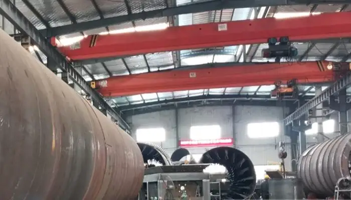
Main characteristics:
- Relatively compact bridge structure.
- Lower structural dead weight in many configurations.
- Suitable for many standard workshop applications.
- Can be designed with different spans and lifting heights.
Typical preliminary capacity range: 3–10 ton, depending on span, duty, and engineering design.
Double Girder Overhead Crane
A double-girder overhead crane uses two main bridge girders supporting a trolley or hoisting mechanism.
It is commonly considered for:
- Heavy cylindrical shell handling.
- Large silo assembly.
- Heavy structural fabrication.
- Higher lifting height requirements.
- More demanding operating duties.
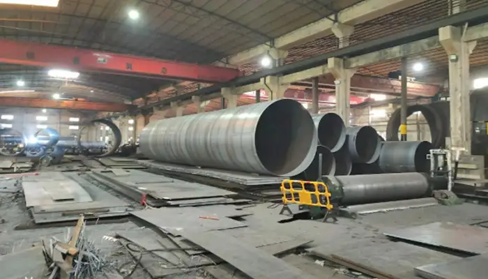
Main characteristics:
- Suitable for higher lifting capacities.
- Can accommodate open-winch hoisting systems.
- Provides flexibility for heavy-duty trolley configurations.
- Can be engineered for demanding industrial applications.
Typical preliminary capacity range: 10–50 ton or higher.
Low Headroom Overhead Crane
A low-headroom overhead crane is designed to reduce the space required between the hook and the crane runway structure.
It can be considered when:
- Workshop roof height is limited.
- The factory requires greater usable hook height.
- Existing building dimensions restrict conventional crane arrangements.
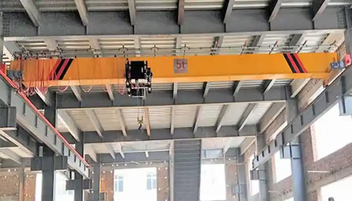
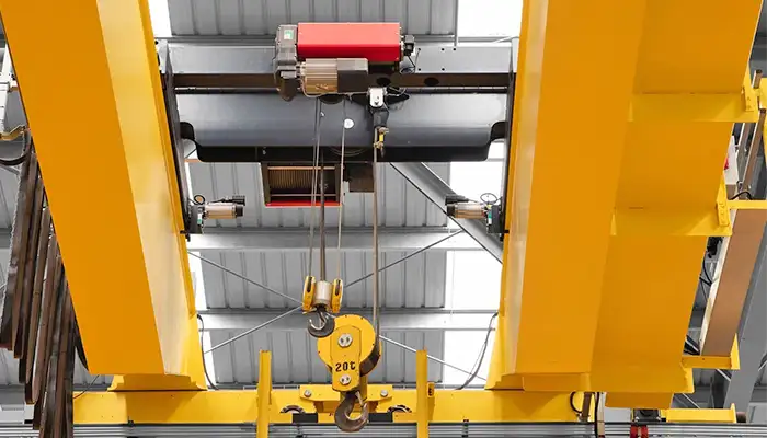
The final design depends on the available headroom, hook approach, lifting height, and runway arrangement.
Single Girder vs. Double Girder Overhead Crane
| Comparison Factor | Single Girder Crane | Double Girder Crane |
|---|---|---|
| Main structure | One bridge girder | Two bridge girders |
| Typical applications | Light and medium fabrication | Medium and heavy fabrication |
| Lifting capacity | Often lower | Suitable for higher capacities |
| Trolley arrangement | Commonly electric hoist | Hoist trolley or open winch |
| Headroom | Depends on hoist design | Depends on trolley and hoist arrangement |
| Heavy assembly | Subject to engineering | Commonly preferred |
| Investment | Often lower for comparable standard applications | Generally higher for comparable configurations |
The choice should be based on rated capacity, span, lifting height, duty, wheel loads, building structure, and total project cost rather than crane type alone.
What Lifting Attachments Are Required for Silo Manufacturing?
The lifting attachment is an important part of the crane system. Different materials and fabricated components require different lifting methods. The following sections cover plate clamps, coil C-hooks, spreader beams, customized lifting frames, and how to match lifting attachments with crane capacity.
Plate Clamps and Plate Lifting Devices
Plate clamps are used to lift and move individual steel plates.
Selection considerations:
- Plate thickness.
- Plate surface condition.
- Horizontal or vertical lifting.
- Number of plates handled at one time.
- Required lifting orientation.
Steel Coil C-Hooks and Coil Lifters
C-hooks and coil lifting devices are used to handle steel coils.
Important selection parameters:
- Coil weight.
- Coil inside diameter.
- Coil outside diameter.
- Coil width.
- Horizontal or vertical coil orientation.
Spreader Beams and Lifting Beams
Spreader beams and lifting beams are useful for handling long plates, cylindrical sections, and large fabricated components.
They help distribute lifting forces across multiple lifting points when properly designed.
Selection considerations:
- Beam length.
- Rated capacity.
- Lifting point spacing.
- Load center of gravity.
- Deflection and structural strength.
Customized Lifting Frames
Customized lifting frames may be required for:
- Large cylindrical shell sections.
- Hopper and cone structures.
- Irregularly shaped components.
- Large fabricated assemblies.
The lifting frame should be designed according to the component geometry, lifting points, and required handling orientation.
How to Match Lifting Attachments with Crane Capacity
Before selecting the crane, buyers and engineers should verify:
- Maximum component weight.
- Attachment self-weight.
- Rigging and sling weight.
- Load center of gravity.
- Number and position of lifting points.
- Component strength and deformation limits.
- Applicable lifting design and safety requirements.
A lifting attachment must be included in the suspended-load calculation, not treated as an independent accessory outside the crane capacity.
How to Select the Right Overhead Crane for a Silo Factory
Before requesting a crane quotation, prepare the following information. Examples are provided to help you complete the requirements.
- Lifting Capacity: ______ ton (Example: 20 ton maximum load)
- Crane Span: ______ m (Example: 28 m)
- Lifting Height: ______ m (Example: 10 m)
- Runway Length: ______ m (Example: 80 m)
- Working Duty: ______ (Example: ISO A5 / FEM 2m)
- Power Supply: ______ (Example: 400 V, 50 Hz, 3-phase)
- Working Environment: ______ (Example: Indoor, normal temperature, dusty workshop)
Additional Requirements: ______ (Example: VFD control, remote control, anti-collision protection)
Providing these details helps the crane manufacturer recommend a suitable overhead crane capacity, configuration, and lifting system for your silo manufacturing workshop.
Example Technical Selection Worksheet
| Selection Parameter | Example Requirement |
|---|---|
| Application | Cylindrical silo shell assembly |
| Maximum component weight | 8 ton |
| Lifting attachment weight | 2 ton |
| Total suspended load | 10 ton |
| Shell dimensions | Ø 8 m × 2 m |
| Crane span | 25 m |
| Runway length | 60 m |
| Lifting height | 10 m |
| Working duty | To be confirmed from load spectrum |
| Power supply | 400 V / 50 Hz / 3-phase, example only |
| Crane type | Double girder, subject to engineering review |
This worksheet is an example of the information needed for preliminary crane selection. Final crane capacity and configuration must be verified against the actual lifting arrangement and building structure.
Example Overhead Crane Configurations for Silo Manufacturing Factories
The following examples illustrate how different crane capacities and configurations may be applied in silo manufacturing workshops, covering general fabrication, shell assembly, and heavy silo manufacturing.
5–10 Ton Overhead Crane for General Fabrication
Typical applications:
- Steel plate handling.
- Cutting and preparation.
- Plate rolling.
- Small shell component handling.
Illustrative configuration:
- Capacity: 5–10 ton.
- Span: 16–22 m.
- Lifting height: 6–10 m.
- Crane type: Single or double girder, subject to engineering.
- Lifting equipment: Plate clamps or lifting beam.
- Control: Pendant or radio remote control.
15–20 Ton Double Girder Overhead Crane for Shell Assembly
Typical applications:
- Medium and large cylindrical shell handling.
- Shell section alignment.
- Welding and assembly operations.
- Hopper and structural component handling.
Illustrative configuration:
- Capacity: 15–20 ton.
- Span: 20–25 m.
- Lifting height: 8–12 m.
- Crane type: Double girder.
- Lifting equipment: Customized spreader beam.
- Control: Radio remote control or cabin, depending on the operation.
- Optional feature: Variable frequency drives for controlled movement.
30–50 Ton Double Girder Overhead Crane for Heavy Silo Manufacturing
Typical applications:
- Large cylindrical shell assemblies.
- Heavy hopper structures.
- Large fabricated components.
- Heavy-duty production and assembly areas.
Illustrative configuration:
- Capacity: 30–50 ton.
- Span: 22–31.5 m.
- Lifting height: 10–15 m.
- Crane type: Double girder.
- Lifting equipment: Engineered lifting frame or spreader beam.
- Control: Cabin or radio remote control.
- Optional feature: VFD-controlled hoisting and travel.
All example configurations are preliminary references. Final specifications depend on the actual component drawings, building dimensions, runway conditions, lifting accessories, and operating duty.
Crane Design, Controls and Safety Features
An overhead crane for silo manufacturing should be designed according to the load, lifting height, positioning accuracy, and workshop environment. Consider the following technical requirements:
- Hoisting System: Electric wire rope hoist or open-winch system; single hook or customized multi-point lifting arrangement. (Example: 10 ton wire rope hoist or 30 ton open-winch system.)
- Speed Control: VFD for hoisting, trolley travel, and crane travel. (Example: Hoisting speed 0.5–5 m/min; travel speed 5–30 m/min, depending on the application.)
- Operating Controls: Pendant control, radio remote control, operator cabin, or combined control. (Example: Radio remote control for shell positioning and welding operations.)
- Safety Devices: Overload limiter, upper and lower limit switches, emergency stop, travel limit switches, warning lights and alarms, and anti-collision protection where required.
- Lifting Attachments: Standard hooks, spreader beams, plate clamps, or customized lifting frames. (Example: A multi-point lifting beam for handling large cylindrical shell sections.)
- Lifting Safety: Check the load weight, center of gravity, lifting points, attachment capacity, and shell deformation. Keep the lifting path clear and follow an approved lifting plan.
Final hoisting speeds, crane configurations, and safety devices should be determined by the actual load, working duty, operating conditions, and applicable standards.
Factory Layout and Installation Requirements
Before installing an overhead crane, check the factory dimensions, runway structure, and production layout. These details affect crane design, installation, and safe operation.
- Building Dimensions: Building width ____ m (Example: 30 m); building length ____ m (Example: 100 m); building height ____ m (Example: 12 m).
- Crane Runway: Rail span ____ m (Example: 28 m); runway length ____ m (Example: 90 m); rail elevation ____ m; available headroom ____ m.
- Building Structure: Provide runway beam drawings, column dimensions, connection details, and existing structural drawings. The structure must be checked for crane wheel loads, vertical and horizontal forces, and beam strength and stiffness.
- Crane Coverage: Identify the areas requiring lifting, such as raw material storage, plate cutting, rolling, shell welding, hopper fabrication, final assembly, and finished product dispatch.
- Installation Conditions: Confirm access for crane transportation and lifting, installation space, electrical supply, and available installation equipment.
- Installation and Commissioning: The project may include crane assembly, electrical connections, inspection, load testing, commissioning, operator training, and maintenance handover.
Example: A silo factory has a 30 m wide × 100 m long workshop, with a crane runway span of 28 m and a runway length of 90 m. These dimensions provide a starting point for evaluating the crane layout. The runway beams, columns, connections, and foundations must still be checked against the proposed crane's maximum wheel loads and operating forces.
Recommendation: Provide the factory layout and existing building drawings before crane design. This allows the engineering team to check crane dimensions, runway compatibility, structural loads, and installation requirements.
Common Mistakes When Selecting an Overhead Crane for Silo Manufacturing
Avoiding common selection mistakes helps reduce operating risks and costly modifications. The following sections list seven common mistakes and provide an inquiry checklist to help buyers prepare the technical information needed for a suitable overhead crane recommendation.
Mistake 1: Selecting Crane Capacity Based Only on the Steel Component Weight
The lifting attachment, spreader beam, slings, and other suspended equipment must also be included.
Mistake 2: Ignoring Component Dimensions
A large cylindrical shell may require a customized lifting arrangement even when its weight is within the crane's rated capacity.
Mistake 3: Underestimating Lifting Height
The maximum component height, lifting device dimensions, and required clearance must be considered together.
Mistake 4: Selecting a Standard Hook for Every Lifting Operation
Steel plates, coils, cones, and cylindrical sections may require different attachments.
Mistake 5: Ignoring Working Duty
A crane used continuously in a production line may require a different duty classification from one used occasionally for material transfer.
Mistake 6: Failing to Verify Building Structure
Runway beams, columns, and connections must be checked against the proposed crane wheel loads and horizontal forces.
Mistake 7: Ignoring Future Production Requirements
A crane selected only for current loads may not support larger components or increased production capacity in the future.
Technical Information Buyers Should Provide
To recommend a suitable overhead crane, the manufacturer needs information about the lifting loads, workshop dimensions, operating conditions, and electrical supply. The following checklist can help buyers prepare their inquiry.
| Parameter | Information to Provide |
|---|---|
| Crane application | Plate handling / shell assembly / heavy fabrication |
| Maximum load | ton |
| Load dimensions | Length × width × diameter × height (m) |
| Material thickness | mm |
| Material type | Carbon steel / stainless steel / other |
| Lifting attachment | Hook / plate clamp / C-hook / spreader beam |
| Crane capacity | ton, if already determined |
| Crane span | m |
| Runway length | m |
| Lifting height | m |
| Working duty | ISO classification, if known |
| Operating hours | Hours per day |
| Power supply | Voltage / frequency / phase |
| Building dimensions | Width × length × height |
| Existing runway | Drawings or structural information |
| Supporting documents | Component drawings / factory layout / load photographs |
What If You Do Not Have Complete Technical Information?
Not every buyer has finalized crane specifications at the inquiry stage. You can still request a preliminary proposal by providing:
- Photographs of the materials and components to be lifted.
- Available component drawings.
- Estimated maximum load weight.
- Approximate component dimensions.
- Workshop layout or building drawings.
- Description of the manufacturing process.
The engineering team can review the available information and help identify the appropriate crane type, preliminary capacity, lifting arrangement, and additional technical requirements.
FAQs About Overhead Cranes for Silo Manufacturing
Answers to common questions about selecting overhead cranes for silo manufacturing, covering capacity ranges, crane type selection, shell weight calculation, lifting attachments, lifting height, duty classification, span and runway length, and quotation requirements.
What capacity overhead crane is needed for a silo manufacturing factory?
Many silo manufacturing applications use overhead cranes in the 5–30 ton range. Smaller plate-handling operations may require 3–5 ton cranes, while heavy shell assembly and large structural fabrication may require 30–50 ton or higher capacities. The final selection depends on the maximum suspended load, lifting attachments, and operating conditions.
What type of crane is best for lifting cylindrical silo sections?
A double-girder overhead crane is commonly considered for medium and heavy cylindrical shell sections. It can be equipped with a customized spreader beam or lifting frame. The final configuration depends on shell diameter, weight, lifting points, span, and required lifting height.
Is a single-girder or double-girder crane better for silo fabrication?
Single-girder cranes are often suitable for general plate handling and light-to-medium fabrication. Double-girder cranes are commonly preferred for heavier shell assembly, large fabricated structures, and demanding lifting operations. The decision should also consider span, duty, headroom, and building structure.
How do you calculate the weight of a cylindrical silo shell?
For a thin cylindrical steel shell, an approximate calculation is:
Shell weight (kg) ≈ π × Diameter (m) × Height (m) × Thickness (mm) × 7.85.
This provides the basic shell weight. Stiffeners, flanges, reinforcement rings, openings, and other attached components must be added separately.
What lifting attachments are used for steel plate and silo shell handling?
Common attachments include plate clamps, vacuum lifting devices, steel coil C-hooks, spreader beams, lifting beams, and customized lifting frames. The correct device depends on the load shape, dimensions, weight, center of gravity, and lifting orientation.
How much lifting height is required for silo manufacturing?
The required lifting height depends on the maximum component height, the lifting attachment, the workshop layout, and the clearance needed for transportation and assembly. Buyers should provide the maximum height of the components and the required clearance above the floor.
Can one overhead crane handle steel plates, coils, and finished silo sections?
A single overhead crane may handle multiple load types if its rated capacity, lifting attachments, hook arrangement, operating coverage, and lifting procedures are suitable for all intended operations. Specialized attachments or separate cranes may be necessary for different production areas.
What crane duty classification is suitable for a silo manufacturing workshop?
The appropriate duty classification depends on lifting frequency, load spectrum, operating hours, and working cycles. ISO 4301 and applicable FEM classifications can be used to determine the required duty. The engineering team should evaluate actual operating conditions before assigning a classification.
How do you determine the required crane span and runway length?
The crane span is determined by the distance between the runway rail centerlines and the required working coverage across the workshop. Runway length depends on the longitudinal production area that needs to be served. Building drawings and the factory layout are useful for determining both dimensions.
What information is required to get an overhead crane quotation?
The most important information includes maximum load weight, component dimensions, lifting height, crane span, runway length, operating duty, power supply, and building dimensions. Component drawings, photographs, and factory layout drawings can help the manufacturer prepare a more accurate technical proposal.
Get an Overhead Crane Solution for Your Silo Manufacturing Factory
Every silo manufacturing facility has different material dimensions, production processes, lifting requirements, and workshop conditions. Selecting the right overhead crane requires evaluating these factors together.
Yuantai Crane provides customized overhead crane solutions for industrial material handling and steel fabrication applications. From general steel plate handling to heavy cylindrical shell assembly, crane configurations can be developed according to your lifting capacity, span, lifting height, working duty, and factory layout.
Send us your project requirements to receive a preliminary crane recommendation and technical proposal.
To help our engineering team evaluate your application, please provide:
- Maximum load weight and component dimensions.
- Lifting attachment requirements.
- Required crane span and lifting height.
- Runway length and building dimensions.
- Production process and operating frequency.
- Available drawings, photographs, or factory layout.
Yuantai Crane – Your Overhead Crane Manufacturing and Engineering Partner.

Article by Bella ,who has been in the hoist and crane field since 2016. Bella provides overhead crane & gantry crane consultation services for clients who need a customized overhead travelling crane solution.Contact her to get free consultation.
Related Products

Yuantai Cranes
Overhead Crane Manufacturer with CE, ISO, SGS, CNEX Certificates.
- Main Specifications - Capacity: 0.5–550 tons | Span: up to 40m | Speed: 0.8–12 m/min | Duty: A3–A7 | Power: 380–690V, 50/60Hz | Control: pendant/remote/cabin
- Full engineering: FEA/PLC/VFD + in-house build + global delivery + on-site support, for workshops, factories, EPC contractors, industrial projects, etc.
- Support: design, manufacturing, testing, service – end-to-end, customized lifting solutions worldwide.
How to Get an Accurate Crane Price for Your Application?
Tips: Copy the spec list, fill in your details, and paste it into the form on the right/ down-below for a quick price.
- Crane type:_____ . (e.g., overhead crane, gantry crane, jib crane)
- Max weight to lift:_____ tons. (e.g., 2t, 5t, 10t, 20t, 50t)
- Lifting height:_____ m. (How high does the hook need to reach?
- Workshop width (span):_____ m . (Distance between the two crane rails)
- Travel distance:_____ m . (How long does the crane need to move along the runway?)
- Control type:_____. (Pendant / remote / cabin Control)
- Power supply:_____. (Local voltage & frequency – e.g., 380V, 50Hz, 3-phase)
- What will it be used for?_____ (e.g., steel fabrication, concrete products, mold handling, general manufacturing, etc.)
- Any special requirements?_____ (e.g., extreme temperature, dusty or explosive environment, special paint color, etc.)
Just leave a message via the contact form and our hoist and crane engineer will contact you with in 24working hours.
Get Your Custom Quote–Quick & Easy
Fill in what you know. Skip what you don't – we'll help.Any question will be reply with 24 working hours