Grab Overhead Crane Selection: Loads, Capacity & Applications
Content Quick Link
How to Select a Grab Overhead Crane for Different Materials and Applications
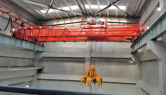
A grab bucket overhead crane picks up loose bulk materials and awkward loads, lifts them, moves them and drops them where they're needed. You'll find these cranes in coal power plants, biomass facilities, cement factories, mines, steel plants, waste-to-energy plants and bulk storage warehouses.
The tricky part is that for each application, the material handling crane needs to be tailored as per the specific conditions and applicaiton requirments. Coal sitting in a bunker is a very different problem from iron ore, steel scrap or mixed household waste. Density, particle size, moisture, how much you need to move and how often you need to move it all shape the choice of grab bucket and crane.
So before you start shopping, it helps to answer a few basic questions:
- What exactly will the crane be picking up?
- Do you need a clamshell grab or an orange-peel grab?
- Should the grab open and close by ropes or by hydraulics?
- How much capacity do you need, and how big should the bucket be?
- What span, lifting height and travel distance does your building allow?
- Will the crane actually fit in the space you have?
- Do you want a cabin operator, a radio remote, or full automation?
This guide walks through each of these in plain terms, using real industrial examples.
What Materials or Objects Do You Need to Handle?
The first thing to consider when selecting a grab overhead crane is the material you need to handle. Coal, iron ore, wood chips and scrap metal all have different characteristics. They vary in bulk density, particle size, shape, moisture content and weight. These differences affect the type of grab bucket, its capacity and the crane configuration you need. Let's look at some common applications and the crane arrangements typically used for each one.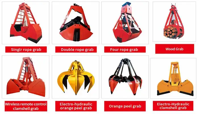 12 types of grab bucket for different loading material and objects handing
Coal, Lignite and Biomass Handling
Coal and biomass are commonly handled by grab overhead cranes in power plants, fuel storage facilities and industrial boiler houses.
Depending on the facility, the material may include bituminous coal, lignite, wood chips, biomass pellets, sawdust or other agricultural biomass. Typical handling locations include coal bunkers, fuel storage halls, coal warehouses and boiler feeding systems.
For these applications, a clamshell grab overhead crane is generally a suitable choice.
Recommended crane configuration
- Crane type: Double girder overhead travelling crane with a grab trolley.
- Grab bucket: Two-shell clamshell grab. A mechanical four-rope grab is commonly used for coal handling. An electro-hydraulic grab is another option when a simpler rope arrangement is preferred.
- Typical crane capacity: 5–32 tons, with grab bucket volumes of approximately 3–12 m³.
- Typical configurations: A coal bunker crane may use a 16-ton capacity with a 5 m³ grab bucket. Larger fuel storage halls may require a 20–25-ton crane with an 8–10 m³ bucket.
- Duty class: A6–A7 (FEM 4m–5m) for continuous fuel handling.
Why does bucket volume matter?
Coal and biomass have very different bulk densities. This directly affects how much material a grab bucket can carry in one cycle.
For reference:
- Bituminous coal: approximately 0.75–0.95 t/m³.
- Lignite: approximately 0.65–0.75 t/m³.
- Wood chips: approximately 0.2–0.4 t/m³.
Take wood chips as an example. Because they are much lighter than coal, a larger bucket is usually needed to move the same weight of material in one lift.
This is why you should not select a grab bucket based on volume alone. The bulk density of your actual material must be considered when calculating the required lifting capacity.
What should you check before ordering?
Before selecting a coal handling grab crane or biomass grab crane, confirm the following:
- The actual bulk density of the material at your facility.
- Moisture content and particle size.
- Required material feeding rate, usually measured in tons per hour.
- Expected bucket filling efficiency. For coal, a fill factor of approximately 0.75–0.90 is a common starting point.
- Dust conditions and potential fire or explosion risks. Standard dust protection should not be confused with explosion-proof protection.
- Daily operating hours and the number of lifting cycles.
- Hopper dimensions and material discharge requirements.
These details help determine whether a standard clamshell grab crane is suitable or whether a more specialized configuration is needed.
Iron Ore, Copper Ore and Other Mineral Handling
Mining operations and mineral processing plants often use heavy-duty grab overhead cranes to transfer ore between storage areas, processing equipment and loading points.
Typical materials include iron ore, copper ore, manganese ore, mineral concentrates and other granular minerals. Limestone and similar materials may also be handled in these facilities.
Because ore is generally much denser and more abrasive than coal or biomass, both the grab bucket and the crane structure need to be designed for heavier loading conditions.
Recommended crane configuration
- Crane type: Heavy-duty double girder overhead travelling crane with a grab trolley.
- Grab bucket: Heavy-duty clamshell grab with reinforced hinges and wear-resistant shell edges. For coarse or irregularly shaped ore, an orange-peel grab may be worth considering, depending on the material.
- Typical crane capacity: 10–50 tons, with grab bucket volumes of approximately 3–15 m³.
- Duty class: A6–A7 (FEM 4m–5m). A7 is commonly considered for demanding, continuous mineral handling operations.
How does ore density affect crane capacity?
Iron ore has a relatively high bulk density, typically around 1.6–3.2 t/m³, depending on its composition, moisture content and particle size.
For example, consider a 5 m³ clamshell grab handling ore with a bulk density of 2.4 t/m³. If the bucket achieves an 82% filling factor, the estimated material payload is:
5 × 2.4 × 0.82 = 9.84 tons.
This is the material weight alone. You must also account for the dead weight of the grab bucket when determining the required crane lifting capacity.
For dense materials, a relatively small bucket can already produce a substantial load. Selecting an oversized grab without checking the payload can easily result in an unsuitable crane configuration.
What should you check before ordering?
- Confirm the bulk density, moisture content and maximum material weight per lift.
- Check the particle size and whether the material contains large lumps.
- Consider abrasion. Ore can wear down grab shells, cutting edges and hinges quickly, so wear-resistant materials and replaceable wear plates may be necessary.
- Check the structural strength of the grab bucket, particularly where impact loading is expected.
- Confirm the required handling capacity in tons per hour.
- Select the crane duty class according to actual operating hours and lifting cycles.
For iron ore and other abrasive minerals, the grab bucket's wear resistance and structural strength are just as important as its nominal capacity.
Clinker, Limestone, Sand and Aggregate Handling
Cement plants and building material facilities handle a wide range of bulk materials, including clinker, limestone, gypsum, sand, gravel and crushed stone.
Grab overhead cranes are commonly installed in clinker storage halls, limestone warehouses, aggregate storage buildings and material transfer areas.
The right configuration depends on the material's density, temperature and abrasiveness, as well as the required handling rate.
Recommended crane configuration
- Crane type: Double girder overhead travelling crane with a grab trolley. A single girder grab crane may also be suitable for lighter aggregate handling applications.
- Grab bucket: Clamshell grab with abrasion-resistant shells. For hot clinker applications, check whether heat-resistant bearings, seals and other components are required. Electro-hydraulic grabs may also need hydraulic oil suitable for the operating temperature.
- Typical crane capacity: 5–25 tons, with grab bucket volumes of approximately 2–10 m³.
- Typical configurations: Clinker handling cranes often use a 10–20-ton lifting capacity with a 4–8 m³ grab bucket.
- Duty class: A5–A6 (FEM 3m–4m) for clinker and limestone handling. A4–A5 may be suitable for less demanding aggregate warehouse operations.
Pay attention to material temperature and abrasion.
Clinker is particularly abrasive, and its temperature can remain high after leaving the cooler. Depending on the process, the material may still be around 80–150°C or higher when collected by the grab bucket.
Don't assume that the clinker has cooled to room temperature by the time it reaches the crane. The actual temperature at the pickup point should be confirmed before specifying the grab and its components.
Typical bulk density references include:
- Clinker: approximately 1.2–1.5 t/m³.
- Limestone: approximately 1.5–1.7 t/m³.
- Sand: approximately 1.5–1.8 t/m³.
What should you check before ordering?
- Maximum material temperature at the grab pickup location.
- Actual bulk density and particle size.
- Abrasion resistance of the grab shells, cutting edges and hinges.
- Required bucket filling efficiency.
- Material handling capacity per hour.
- Storage pile dimensions and hopper opening size.
For hot clinker handling, temperature protection and wear resistance should be considered during the initial design rather than added after the crane has been manufactured.
Scrap Metal and Steel Production Materials
Scrap metal handling is different from handling coal, sand or other loose bulk materials.
Scrap comes in irregular shapes and sizes. It may include steel offcuts, metal pieces, tangled scrap, mixed steel waste and other recycled materials. A conventional clamshell grab is generally unsuitable for these loads because the material needs to be gripped rather than simply scooped.
For this reason, steel plants and scrap recycling facilities commonly use an orange-peel grab overhead crane.
Typical applications include scrap yards, steel mills, metal recycling plants, scrap storage areas and electric arc furnace charging systems.
Recommended crane configuration
- Crane type: Heavy-duty double girder overhead travelling crane with a grab trolley, designed for impact-heavy operation.
- Grab bucket: Orange-peel grab with 4–6 curved tines. The grab should have a reinforced structure, strong gripping components and wear-resistant tine tips.
- Typical crane capacity: 10–32 tons, with orange-peel grab volumes of approximately 0.5–6 m³.
- Typical application: Electric arc furnace charging cranes often use capacities in the 16–25-ton range.
- Duty class: A7 (FEM 5m) for steel mill charging. A6–A7 for scrap yard handling.
Why choose an orange-peel grab for scrap metal?
The curved tines can open around irregular scrap pieces and close to grip the material. This makes the orange-peel grab more suitable for bulky and tangled scrap than a conventional clamshell bucket.
One important point is that scrap metal does not fill a grab bucket in the same way as coal or sand.
The filling factor of an orange-peel grab handling scrap may be around 0.50–0.70. For example, a 5 m³ grab may only hold approximately 2.5–3.5 m³ of actual scrap material.
The actual payload depends on the shape, density and arrangement of the scrap. Crane capacity should therefore be calculated using realistic loading conditions rather than assuming the bucket will be completely filled.
What should you check before ordering?
- What type of scrap will you handle?
- What are the typical and maximum dimensions of individual scrap pieces?
- How much gripping force is required?
- What tine closing force is needed?
- What grab opening diameter is required?
- What materials should be used for the tines and wear-resistant components?
- Will the grab experience frequent impact during loading and unloading?
- What is the required payload per cycle?
- Where does the crane need to discharge the scrap, such as a storage area, charging hopper or furnace?
For scrap handling, the grab's opening size, gripping force and structural strength are important selection factors. A crane with sufficient lifting capacity may still be unsuitable if the grab cannot handle the actual shape and size of the scrap.
Municipal Solid Waste, Industrial Waste and RDF Handling
Waste-to-energy plants and waste treatment facilities use grab overhead cranes to collect, mix, move and feed waste from storage bunkers into processing equipment or incinerators.
The material may include municipal solid waste (MSW), industrial waste, refuse-derived fuel (RDF), mixed combustible waste and bulky waste.
Unlike conventional bulk material handling, the crane in a waste bunker often performs several operations throughout the day. It receives incoming waste, moves it around the bunker, mixes different materials and feeds the incinerator hopper.
A waste handling grab crane therefore needs to be designed for frequent operation and the specific conditions inside the bunker.
Recommended crane configuration
- Crane type: Double girder overhead travelling crane with a grab trolley. Electrical and mechanical components should be suitably protected against the dusty and humid bunker environment.
- Grab bucket: Orange-peel grab with a sufficiently large opening for mixed and irregular waste. A clamshell grab may be suitable for more uniform waste streams.
- Typical crane capacity: 10–25 tons, with grab bucket volumes of approximately 3–12 m³.
- Typical configurations: Waste-to-energy bunker cranes commonly use 16–20-ton lifting capacities with 6–10 m³ orange-peel grabs.
- Duty class: A7–A8 (FEM 5m) for facilities operating 16–24 hours per day.
What makes a waste bunker crane different?
The crane needs to do more than lift waste from one location to another.
It may need to:
- Collect incoming waste from the bunker.
- Move waste to different storage positions.
- Mix materials to maintain a more consistent fuel composition.
- Feed waste into the incinerator hopper.
- Position the grab accurately above the feeding chute.
This means the crane needs reliable grab opening and closing functions, smooth movement and accurate positioning. Repeated operation at relatively low lifting heights also needs to be considered when selecting the hoisting mechanism and duty class.
What should you check before ordering?
- Waste composition and the proportion of bulky or irregular materials.
- Moisture content and the possibility of corrosion inside the bunker.
- Grab opening dimensions, especially when handling large or tangled waste.
- Required mixing, collecting and feeding functions.
- Corrosion protection for the crane structure and hydraulic components. Suitable epoxy coatings and protected hydraulic parts may be necessary.
- Operating hours and expected lifting cycles. A7 or A8 duty is common for continuously operated waste facilities.
- Operator visibility and control requirements.
- Whether semi-automatic or fully automatic operation is needed.
For a waste-to-energy project, the crane should be designed around the complete bunker operation, not just the weight of the waste being lifted.
Other Bulk Materials and Irregular Loads
Grab overhead cranes can also be used for other industrial materials, including fertilizer, suitable bulk chemicals, foundry sand, cooled slag, industrial by-products and construction and demolition waste.
For many of these applications, a double girder grab crane with a clamshell bucket in the 5–20-ton capacity range may be a starting point. The final configuration depends on the material and the actual operating conditions.
If your material is particularly hot, corrosive, hazardous or irregularly shaped, the grab bucket and crane protection need to be assessed individually.
For example, handling cooled slag is different from handling hot slag. Similarly, a standard grab crane should not be assumed suitable for molten materials. Molten metal and other molten substances require specialized lifting and handling equipment designed specifically for those hazards.
Which Grab Bucket Type Is Suitable for Your Materials?
After identifying the material you need to handle, the next step is to choose the right grab bucket. The two most common options for grab overhead cranes are clamshell grabs and orange-peel grabs. Although both are used to collect and move bulk materials, their structures and working methods are quite different. A clamshell grab is generally used for loose, granular materials such as coal, sand, limestone and ore. An orange-peel grab is better suited to irregular materials that need to be gripped, such as scrap metal, bulky waste and mixed industrial residues. The choice depends mainly on the material's shape, size, density and condition, as well as how it needs to be collected and discharged.
Clamshell Grab Bucket Overhead Crane
A clamshell grab consists of two opposing shells that open and close to collect material. During operation, the grab is lowered onto the material with its shells open. The shells then close around the material, trapping it inside before the crane lifts and moves it to the discharge point.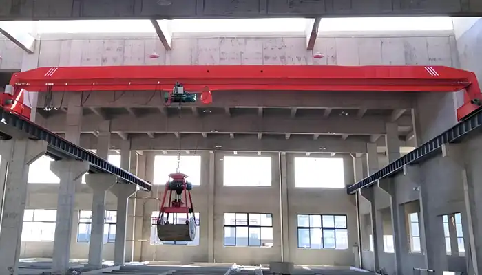
This design works well with loose, free-flowing materials that can be scooped into a bucket.
Common applications include:
- Coal and lignite handling in power plants.
- Wood chips and biomass handling.
- Sand, gravel and aggregate storage.
- Limestone and clinker handling in cement plants.
- Iron ore and other granular mineral handling.
- Bulk material transfer in industrial warehouses.
For these applications, the clamshell grab bucket is usually the first option to consider.
What should you consider when selecting a clamshell grab?
The bucket volume is an important starting point, but it is not enough to determine whether the grab is suitable. You also need to consider the material density, bucket opening and the force required to close the shells.
The main selection parameters include:
- Bucket volume: Commonly ranges from 3 m³ to 25 m³ or more, depending on the application.
- Opening width: Must be suitable for the material pile, hopper or receiving area.
- Shell geometry: Affects how the bucket penetrates the material, collects it and releases it.
- Material bulk density: Determines the weight of material carried in each cycle.
- Filling factor: Typically around 0.75–0.90 for granular materials, depending on material conditions and grab design.
- Closing force: Must be sufficient to collect the material effectively.
- Wear resistance: Particularly important when handling abrasive materials such as ore, clinker and crushed stone.
Mechanical or electro-hydraulic clamshell grab?
Clamshell grabs are available in different operating designs, including two-rope, four-rope and electro-hydraulic types.
A mechanical four-rope grab is commonly used with a dedicated grab trolley on an overhead crane. Its opening and closing movements are controlled through the hoisting ropes.
An electro-hydraulic grab uses a hydraulic system to open and close the shells. It can simplify the rope arrangement, although the hydraulic power unit and electrical connections need to be considered in the crane design.
The choice should be made together with the crane configuration. The grab, trolley, hoisting mechanism and control system must work as one complete system.
Don't forget the grab's own weight.
One point that buyers sometimes overlook is the dead weight of the grab bucket.
A mechanical four-rope clamshell grab designed for a 10–25-ton handling application may weigh approximately 4–9 tons when empty, depending on its size and construction.
This weight is part of the load carried by the crane. When calculating the required crane capacity, you must account for both the grab's dead weight and the material payload.
For example, a crane designed to lift a 15-ton material load with a 6-ton grab needs a lifting arrangement capable of supporting their combined weight, subject to the applicable crane rating and design requirements.
Orange-Peel Grab Bucket Overhead Crane
An orange-peel grab uses several curved tines arranged around a central body. The tines open to surround the material and then close to grip and collect it.
Unlike a clamshell bucket, which collects material between two shells, an orange-peel grab can grip objects from several directions. This makes it more suitable for irregular, bulky or tangled materials.

Typical applications include:
- Steel scrap and metal offcuts.
- Irregular metal pieces in recycling plants.
- Mixed industrial waste.
- Bulky municipal solid waste.
- Coarse and irregular industrial residues.
- Certain types of irregular minerals and scrap materials.
For scrap metal handling, an orange-peel grab overhead crane is generally a more suitable choice than a conventional clamshell grab crane.
What should you consider when selecting an orange-peel grab?
The most important factors are the size and arrangement of the tines, the opening diameter and the gripping force.
The main selection parameters include:
- Number of tines: Usually 4–6, depending on the material and required gripping arrangement.
- Opening diameter: Must be large enough to collect the largest pieces of material you expect to handle.
- Gripping force: Determines how securely the grab can hold irregular materials.
- Tine geometry: Affects how the tines enter the material and close around it.
- Grab dead weight: Mechanical orange-peel grabs may weigh approximately 5.5–20 tons, depending on their size and capacity.
- Wear resistance: Important when handling scrap, sharp metal edges and abrasive waste.
- Impact resistance: The grab structure and tine connections must withstand repeated loading impacts.
Why does the opening diameter matter?
Consider a scrap yard handling a mixture of steel offcuts, tangled scrap and relatively large metal pieces.
If the grab opening is too small, it may struggle to collect the larger pieces. If the tine arrangement does not match the shape of the scrap, the grab may fail to grip the load securely.
This is why the largest individual piece of material, not just the average scrap size, should be considered during grab selection.
The same applies to waste handling. A grab used for relatively uniform industrial waste may have different opening and tine requirements from one handling bulky municipal solid waste.
An orange-peel grab is particularly useful when the material cannot be collected effectively by simply closing two opposing shells around it.
Both grab types are used for bulk material handling, but they are designed for different material conditions.
The following comparison can help you identify which type is more suitable for your application.
| Selection factor | Clamshell grab | Orange-peel grab |
|---|---|---|
| Grab structure | Two opposing shells | Multiple curved tines |
| Typical materials | Granular and loose materials | Irregular, coarse and mixed materials |
| Common loads | Coal, sand, clinker and ore | Scrap metal, bulky waste and mixed residues |
| Typical filling factor | 0.75–0.90 | 0.50–0.70 |
| Main design priority | Bucket volume and filling efficiency | Gripping force and tine strength |
| Important material parameters | Bulk density and particle size | Piece dimensions, shape and arrangement |
| Common applications | Power plants, cement plants and bulk warehouses | Scrap yards, recycling plants and waste handling facilities |
How do you make the final choice?
Don't select a grab bucket simply because it is commonly used in your industry. The actual material condition is more important than the application name.
For example, two waste treatment plants may require completely different grab configurations. One may handle relatively uniform, loose waste that can be collected with a clamshell grab. Another may deal with bulky, tangled waste that requires an orange-peel grab.
Similarly, an ore handling application does not automatically mean that every type of grab will be suitable. Particle size, lump dimensions, bulk density and material flow characteristics all need to be considered.
Before finalizing the grab design, confirm:
- What material will the crane handle?
- Is it loose and granular, or bulky and irregular?
- What are the material's bulk density and particle size?
- What is the largest individual piece that needs to be collected?
- What bucket volume or opening diameter is required?
- How much material needs to be handled per hour?
- What are the operating conditions, including dust, moisture, temperature and abrasion?
Once these details are clear, the grab type and its specifications can be matched to the crane's lifting mechanism, trolley and operating duty.
What Type of Grab Overhead Crane Should You Choose?
After selecting the grab bucket, the next step is to decide how it will open and close. This is an important part of the crane design because the operating mechanism affects the trolley configuration, hoisting system, electrical arrangement and maintenance requirements. For grab overhead cranes, two common options are mechanical rope-operated systems and electro-hydraulic systems. Both can be used with suitable grab bucket designs, but they work differently. The right choice depends on the material you handle, the required lifting cycles, the crane configuration and the maintenance conditions at your facility.
Mechanical Rope-Operated Grab Overhead Crane
A mechanical rope-operated grab crane uses a system of wire ropes to lift, support, open and close the grab bucket.
Depending on the design, the system can use two ropes or four ropes. These arrangements differ in how the hoisting and closing movements are controlled.
Two-rope grab system
A two-rope grab uses one supporting rope and one closing rope.
The two ropes work together to control the grab's lifting, opening and closing movements. This arrangement has a relatively simple rope configuration and is used for suitable grab applications.
Four-rope grab system
A four-rope grab uses two supporting ropes and two closing ropes.
The supporting ropes lift and lower the grab, while the closing ropes control the opening and closing movements. Because these functions are separated, the system provides independent control of the hoisting and closing actions.
Four-rope grab systems are commonly considered for heavier-duty applications and deeper material penetration, where sufficient and consistent closing force is important.
What should you consider when selecting a mechanical grab crane?
The rope arrangement needs to be designed together with the crane trolley and hoisting mechanism. It is not simply a matter of attaching a grab bucket to a standard overhead crane.
Important configuration details include:
- Rope arrangement: Whether a two-rope or four-rope system is suitable for the application.
- Supporting and closing ropes: Their functions and required operating movements.
- Hoisting mechanisms: The number and arrangement of hoisting mechanisms needed to operate the grab.
- Rope reeving: The arrangement of drums, sheaves and wire ropes.
- Operating speeds: Hoisting, lowering and grab closing speeds must suit the required handling cycle.
- Grab dead weight: The weight of the empty grab must be included in the crane capacity calculation.
- Maintenance access: Ropes, sheaves, drums and other mechanical components should be accessible for inspection and maintenance.
Mechanical rope-operated grab overhead cranes are widely used for handling coal, sand, clinker, ore and other bulk materials.
What about filling efficiency and closing performance?
A mechanical four-rope clamshell grab can achieve a material-to-grab weight ratio of approximately 1.5–1.9 and a filling rate of 95–100% under suitable conditions.
These figures are not guaranteed operating results. Actual performance depends on the material's flow characteristics, bulk density, particle size, bucket design, pile conditions and operator experience.
For free-flowing materials, a properly matched four-rope grab can provide effective material collection and reliable operation over repeated working cycles.
Electro-Hydraulic Grab Overhead Crane
An electro-hydraulic grab uses an electric motor, hydraulic pump and hydraulic cylinders to open and close the bucket.
When the operator activates the grab, the electric motor drives the hydraulic pump. The pump generates hydraulic pressure, which is directed through the control valves to the cylinders. The cylinders then move the shells or tines to collect or release the material.
Unlike a mechanical rope-operated grab, the opening and closing movements are controlled by the hydraulic system rather than a dedicated closing-rope arrangement.
This can simplify the rope configuration on the crane, although the electrical supply and hydraulic equipment need to be properly integrated.
Electro-hydraulic grabs are used in applications such as scrap metal handling, waste handling, mineral processing and other bulk material operations where hydraulic operation suits the grab design.
What should you consider when selecting an electro-hydraulic grab crane?
The hydraulic system and electrical supply need to match the grab's size, operating speed and working conditions.
Pay attention to the following:
- Motor power: Must be suitable for the hydraulic pump and required operating cycle.
- Hydraulic capacity: Pump flow and working pressure must meet the grab's operating requirements.
- Cylinder force: Must provide sufficient force to open and close the shells or tines.
- Opening and closing time: Affects the overall material handling cycle and required throughput.
- Electrical cable supply: The power supply arrangement must accommodate the grab's movement.
- Cable travel: Cable length and management must cover the full required lifting and trolley travel range.
- Hydraulic oil temperature: Consider the ambient temperature and material conditions, particularly at hot clinker handling facilities and cold outdoor sites.
- Environmental protection: Electrical and hydraulic components need suitable protection against dust, moisture and other site conditions.
- Maintenance requirements: Hydraulic oil, seals, hoses, valves and electrical components need regular inspection.
How is an electro-hydraulic grab supplied with power?
This is an important detail when designing the crane.
The electro-hydraulic grab needs an electrical connection to operate its motor and hydraulic pump. The cable arrangement must allow the grab to move through its full working range without restricting lifting or trolley travel.
The cable reel or other suitable cable management system should therefore be considered as part of the overall crane design.
What about maintenance?
An electro-hydraulic system can eliminate the more complicated closing-rope arrangement used in some mechanical grab systems. This may simplify certain parts of the trolley design and routine mechanical maintenance.
However, it introduces hydraulic components that also require attention.
Regular maintenance may include checking hydraulic oil condition, inspecting seals and hoses, checking for oil leakage and maintaining the motor, pump and control valves.
The decision should be based on the maintenance capabilities available at your facility, not just the initial crane configuration.
Mechanical vs. Electro-Hydraulic Grab Systems: Which Is Better?
Both systems can provide reliable material handling when properly designed. The difference lies in how the grab operates and what equipment is required to support it.
| Selection factor | Mechanical rope-operated | Electro-hydraulic |
|---|---|---|
| Operating method | Coordinated hoisting and closing ropes | Electric motor, hydraulic pump and cylinders |
| Main components | Wire ropes, sheaves, drums and mechanical grab parts | Motor, pump, valves, cylinders and hydraulic lines |
| Crane compatibility | Requires suitable rope drums, reeving and hoisting arrangements | Requires suitable electrical supply and cable management |
| Opening and closing | Controlled through the rope arrangement | Controlled through the hydraulic system |
| Maintenance focus | Wire ropes, sheaves, drums and mechanical components | Hydraulic oil, seals, hoses, motor and electrical components |
| Main selection priority | Rope arrangement and hoisting mechanism | Hydraulic capacity and electrical supply |
Which system should you choose?
There is no single answer for every grab overhead crane application.
A mechanical four-rope grab may be a suitable choice for a coal handling crane or mineral handling crane where the material is relatively uniform and a dedicated rope-operated system fits the required working cycle.
An electro-hydraulic grab may be worth considering for scrap handling or waste handling applications where the grab design benefits from hydraulic opening and closing.
Before making the decision, consider three things:
- Your material: Does it require scooping, digging or gripping? What closing force and operating movement are needed?
- Your crane configuration: Can the trolley accommodate the required rope arrangement, hydraulic equipment and electrical connections?
- Your maintenance conditions: Which system can your maintenance team inspect and service more easily?
The grab operating system should be selected together with the grab bucket and crane, rather than treated as a separate component.
Once these choices are established, you can move on to calculating the crane's required lifting capacity, including the weight of the grab and the material carried in each cycle.
How to Confirm the Required Grab Overhead Crane Capacity?
Capacity is one of the most important numbers on a quotation. Buyers need to keep three things separate: material payload, grab dead weight and the crane's rated lifting capacity. If you size the crane only from material weight or bucket volume, you'll likely get the specification wrong.
Calculate the Material Weight per Grab
Material payload per grab is estimated from the grab bucket volume, the material bulk density and a filling factor.
Example: a clamshell grab with a 5 m³ bucket handling coal.
| Parameter | Value |
|---|---|
| Grab bucket volume | 5 m³ |
| Coal bulk density | 0.8 ton/m³ |
| Filling factor | 85% (0.85) |
| Material payload per grab | 3.4 ton |
The grab carries about 3.4 tons of coal per cycle under these assumptions. The filling factor isn't fixed. It depends on the material, bucket geometry, operating method and actual loading conditions.
A practical warning: A common mistake is using a 100% fill factor. For clamshell grabs on coal, 0.75–0.90 is realistic. For orange-peel grabs on scrap, 0.50–0.70 is more appropriate. Use a fill factor that's too high and you'll end up with an undersized crane.
Account for Grab Dead Weight
The grab itself has weight, and that has to go into the lifting load. The combined suspended weight is the material payload plus the grab dead weight.
Using the same example, assume the grab weighs 1.5 tons:
| Load component | Weight |
|---|---|
| Coal payload | 3.4 ton |
| Grab dead weight | 1.5 ton |
| Combined material and grab weight | 4.9 ton |
The combined suspended weight is about 4.9 tons, before you add any other suspended components.
Important: The final crane rated capacity has to follow the applicable design and rating convention. Confirm whether the quoted crane capacity includes the grab and other lifting equipment. Don't assume material payload equals the crane's rated capacity.
A practical reference: Heavier grabs carry real weight. A mechanical four-rope clamshell rated for 20 tons working load may weigh 6.5–7.5 tons empty. An electro-hydraulic orange-peel grab in the 1–10 m³ range can weigh 3–8 tons, depending on construction. Always get the actual grab weight from the supplier before you finalize crane capacity.
Determine the Required Material Handling Capacity per Hour
For a production facility, you also need to know how much material the crane must move per hour. Throughput depends on the material payload per grab, an effective operating factor (usually 0.75–0.85 for continuous grab work, allowing for breaks, repositioning and minor delays), and the complete operating cycle time.
The full cycle covers lowering, closing, lifting, loaded travel, discharging and returning empty.
For example, if the crane handles 3.4 tons per cycle, a full cycle takes 90 seconds and the effective operating factor is 80%, the estimated throughput is about 108.8 ton/hour.
That's an estimate based on the stated assumptions. Real throughput depends on the material, travel distances, operator skill, discharge conditions and process interruptions.
A practical note: Cycle time often gets underestimated during planning. In a storage hall, a realistic grab crane cycle (pickup, lift, travel 20–30 m, discharge, return) is often 60–120 seconds. If the crane has to travel far between pickup and discharge, cycle time goes up, and you may need a bigger bucket or faster crane to hit your throughput target.
Select the Crane Duty Classification
Two grab cranes with the same rated capacity may need different designs if they work differently. A crane running a few hours a day with few full-load cycles isn't the same as one running continuously in a waste bunker or power plant.
Key factors include:
- Daily operating hours
- Number of lifting cycles
- Load spectrum
- How often it runs at full load
- Starting and stopping frequency
- Required service life
ISO 4301 and FEM classifications give you a framework for determining crane duty. Base the final classification on the actual load spectrum and operating cycles, not just the industry or rated capacity.
Practical duty class guidance for grab cranes
| Application | Typical ISO 4301 Group | Typical FEM Class | Daily Usage |
|---|---|---|---|
| Maintenance / intermittent grab use | A3–A4 | 1Am–2m | 1–4 hours |
| Cement plant clinker handling | A5–A6 | 3m–4m | 4–8 hours |
| Coal power plant bunker crane | A6–A7 | 4m–5m | 8–16 hours |
| Waste-to-energy continuous feed | A7–A8 | 5m | 16–24 hours |
| Scrap yard heavy-duty | A7 | 5m | 16+ hours |
Source: Adapted from FEM/ISO duty class application guidance.
When in doubt, go one class higher than your first estimate. Upgrading from A5 to A6 components usually adds 5–15% to cost, while replacing an underspecified crane costs far more in downtime and premature failure.
How to Determine Grab Overhead Crane Span, Lifting Height and Travel Distance?
After confirming the material, grab bucket type, and crane configuration, the next step is to determine the required crane dimensions. The three main parameters are crane span, lifting height, and travel distance. These dimensions depend on the building layout, material storage area, feeding equipment, discharge points, and the required working range of the grab bucket. Incorrect measurements can limit the crane's working area or cause interference with building structures, hoppers, conveyors, and other equipment.
How to Determine the Grab Overhead Crane Span?
The crane span is the horizontal distance between the centerlines of the two runway rails on which the crane bridge travels.
It is not necessarily the same as the building width. The span must be determined from the runway rail positions and the required material handling coverage.
When confirming the crane span, check the following:
- Building bay width: Measure the distance between the building columns or the available installation area.
- Runway rail spacing: Confirm the center-to-center distance between the two runway rails. This is the reference dimension for the crane span.
- Material handling coverage: Check whether the grab can reach all required pickup and discharge positions across the building.
- Column and structural arrangement: Confirm that the crane runway beams, columns, brackets, and other structures can support the proposed crane installation.
- Installation clearance: Allow sufficient space between the crane, building columns, walls, roof structures, and other equipment.
Example:
Suppose a bulk material storage building has an internal width of 24 m. The two runway rails are installed with a center-to-center distance of 22 m.
In this case, the required grab overhead crane span is approximately 22 m, not 24 m.
The final span should be based on the actual runway rail centerlines and verified against the building structural drawings.
How to Calculate the Required Lifting Height?
The lifting height of a grab overhead crane is the vertical distance that the grab can travel between its lowest and highest working positions.
For a bulk material handling application, do not determine lifting height from the building height alone. Consider the actual pickup and discharge levels.
For example, a crane may need to:
- Lower the grab into a material stockpile or bunker.
- Pick up material from the lowest required level.
- Lift the loaded grab above the bunker wall or feeding equipment.
- Move the material to a hopper, conveyor, or discharge point.
- Open the grab and release the material without hitting surrounding structures.
Required lifting height = Highest required grab position − Lowest required grab position
Example:
A grab overhead crane is used to transfer coal from a storage bunker to a feeding hopper. Assume:
| Parameter | Example dimension |
|---|---|
| Lowest required grab position | 0.5 m above the floor |
| Highest required grab position | 8.5 m above the floor |
| Vertical working distance | 8.0 m |
| Additional allowance for working clearance | 0.5–1.0 m |
| Preliminary lifting height | 8.5–9.0 m |
The preliminary crane lifting height would therefore be approximately 9 m.
This is an illustrative calculation. The final lifting height must also account for the grab's overall dimensions, rope arrangement, opening and closing position, and the clearance needed to pass over bunker walls or hopper edges.
Important: Check the Building Headroom
The building height must provide enough space for the crane girder, trolley, hoisting mechanism, wire ropes, and grab bucket.
For example, a building with a 12 m internal height does not automatically allow a crane with 12 m lifting height. The crane structure and hoisting equipment also occupy vertical space.
Before confirming the lifting height, check:
- Distance from the floor to the roof structure.
- Distance from the runway rail top to the lowest roof obstruction.
- Crane girder height and trolley installation height.
- Available hoisting mechanism and rope travel.
- Required clearance between the fully opened grab and surrounding structures.
How to Determine Bridge Travel and Trolley Travel?
A grab overhead crane normally has two horizontal travel directions.
Bridge travel is the movement of the entire crane along the runway rails, covering the length of the building.
Trolley travel is the movement of the grab hoisting mechanism across the crane bridge, covering the crane span.
Both movements must be sufficient to cover the complete material handling area.
For example, consider a coal handling building with:
- A storage area at one end of the building.
- A feeding hopper at the opposite end.
- A required bridge travel distance of approximately 55 m.
- A required trolley travel range of approximately 18 m.
The crane should be designed to move the grab between the storage and feeding areas without interference from columns, equipment, or other obstructions.
When determining travel distances, consider the following:
| Parameter | What to check |
|---|---|
| Bridge travel | Distance between the furthest required pickup and discharge positions along the building |
| Trolley travel | Distance between the furthest required pickup and discharge positions across the building |
| End clearance | Space required between the crane or trolley and mechanical end stops, building columns, or other obstacles |
| Working coverage | Whether the grab can reach all required material handling positions |
| Obstructions | Hoppers, conveyors, columns, platforms, pipelines, and other equipment |
The actual travel distances should be confirmed from the building layout and the crane's mechanical limits. The available runway length or bridge span may be greater than the effective working travel.
Example: Preliminary Dimensions for a Grab Overhead Crane
The following example shows how a buyer can organize the main dimensional requirements for a bulk material handling project.
Assume a coal storage and feeding building requires one grab overhead crane to transfer coal from the storage area to a feeding hopper.
| Technical parameter | Example requirement |
|---|---|
| Material handled | Coal |
| Crane type | Grab overhead crane |
| Grab type | Four-rope clamshell grab |
| Crane span | 22 m |
| Preliminary lifting height | 9 m |
| Bridge travel distance | 55 m |
| Trolley travel range | 18 m |
| Pickup location | Coal storage bunker |
| Discharge location | Feeding hopper |
| Working environment | Indoor bulk material handling |
These figures are for preliminary planning only. The final crane dimensions and specifications should be confirmed against the actual building drawings, material handling process, grab dimensions, and equipment arrangement.
What Drawings Should You Provide to the Crane Manufacturer?
To avoid repeated adjustments during the design stage, buyers should provide a building layout or general arrangement drawing showing:
- Building length, width, and internal height.
- Distance between the runway rail centerlines.
- Runway beam positions and building column locations.
- Material storage area and maximum stockpile height.
- Hopper, conveyor, or other discharge equipment positions.
- Lowest material pickup level and highest discharge level.
- Roof structures, pipelines, platforms, and other potential obstructions.
- Required pickup and discharge areas.
A simple layout drawing with dimensions is usually more useful than providing only the building's overall length and width.
Buyer tip: If the building is still under construction, provide the preliminary structural drawings and equipment layout. The crane manufacturer can then check the proposed span, lifting height, and travel range before the runway structure and other building arrangements are finalized.
What Site Conditions Should Be Considered When Selecting a Grab Overhead Crane?
The working environment has a direct impact on the design, protection level, electrical configuration, and maintenance requirements of a grab overhead crane. A crane operating inside a coal-fired power plant, for example, faces different conditions from one handling scrap metal in an outdoor stockyard or clinker in a cement plant. Before selecting a grab overhead crane, confirm the site conditions with the crane manufacturer. This helps determine the appropriate crane structure, motors, electrical components, cable system, protective devices, and surface treatment.
Indoor or Outdoor Installation
First, confirm where the grab overhead crane will operate:
- Indoor production building
- Enclosed bulk material storage warehouse
- Outdoor stockyard
- Partially covered material storage area
- Outdoor runway system without building protection
Indoor cranes are generally protected from direct rain, wind, and sunlight. However, dust, humidity, high temperatures, and corrosive gases may still affect their operation.
Outdoor grab overhead cranes require additional consideration for weather exposure, wind loads, rainwater protection, corrosion, and temperature changes.
Example: Outdoor grab overhead crane
For a crane operating in an outdoor coal stockyard, the design may need to include:
| Design item | Technical consideration |
|---|---|
| Wind load | Design wind speed and applicable operating/non-operating wind conditions |
| Rain protection | Weatherproof electrical enclosures and protected motors |
| Corrosion protection | Suitable primer and finishing coating system |
| Parking safety | Rail clamps, storm anchors, or other wind-resistant devices where required |
| Electrical equipment | Appropriate enclosure protection against rain and dust |
| Temperature | Suitable motors, lubricants, cables, and seals for the local climate |
For example, an outdoor crane may need to operate in a design wind speed of 20 m/s or higher, depending on the project location and applicable design standard. The actual operating and non-operating wind limits must be calculated rather than selected from a general reference value.
Dusty, Humid, Corrosive, or High-Temperature Environments
Bulk material handling areas often contain dust, moisture, corrosive substances, or elevated temperatures. These conditions can shorten the service life of electrical equipment, motors, brakes, bearings, cables, and other crane components if they are not considered during design.
The following table provides preliminary design considerations.
| Site condition | Possible design considerations |
|---|---|
| High dust | Dust-protected motors and electrical enclosures; IP55 as a common starting reference, with IP65 considered for more severe exposure |
| High humidity | Moisture-resistant electrical equipment, anti-condensation heaters, suitable cable protection, and corrosion-resistant coatings |
| Corrosive atmosphere | Suitable epoxy or equivalent coating systems, corrosion-resistant materials, and protected electrical connections |
| Outdoor operation | Weatherproof covers, drainage protection, wind-load design, and suitable parking devices |
| High temperature | Heat-resistant motors, cables, seals, lubricants, and thermal protection |
| Low temperature | Low-temperature-grade steel and materials, suitable lubricants, cold-resistant cables, and electrical heaters where required |
Dust protection: IP55 or IP65
For dusty applications such as coal handling, cement production, mineral processing, and waste treatment, the protection level of motors and electrical enclosures should be considered carefully.
- IP55: Common reference for equipment exposed to dust and water jets. It provides limited dust ingress protection and protection against water jets.
- IP65: Dust-tight protection and protection against water jets. It may be more suitable for equipment exposed to heavy dust or frequent cleaning.
The required IP rating should be determined separately for motors, control panels, junction boxes, and other electrical components. A higher IP rating does not automatically mean the equipment is suitable for every industrial environment.
High-temperature applications
If the crane handles hot clinker, hot waste, or other high-temperature materials, confirm the actual ambient temperature around the crane and the temperature of the material being handled.
For example, clinker may enter a handling area at approximately 80–150°C or higher, depending on the production process and cooling stage.
The material temperature is not necessarily the same as the ambient temperature around the crane. The manufacturer should assess the actual heat exposure and determine whether additional protection is needed for:
- Hoisting and travelling motors
- Brakes and electrical components
- Power and control cables
- Hydraulic hoses and seals
- Lubricants and bearing arrangements
- Protective covers and thermal shields
Low-temperature applications
For outdoor cranes operating in cold regions, the minimum design ambient temperature is important.
For example, a project with a minimum ambient temperature of -20°C or -30°C may require low-temperature-grade materials, suitable lubricants, cold-resistant cables, and electrical cabinet heaters.
The actual material grade and component specifications should be selected according to the project's minimum design temperature and applicable standards.
Combustible dust and explosion protection
Coal dust, biomass dust, and certain industrial powders may create combustible dust hazards under specific conditions.
Ordinary dust protection, such as IP55 or IP65, does not provide explosion protection.
If the working area has a combustible dust or flammable gas hazard, the buyer should provide the hazardous-area classification and relevant explosion-protection requirements.
The crane's electrical equipment, motors, brakes, sensors, and control systems may need to comply with ATEX, IECEx, or other applicable local standards.
The required equipment category, equipment protection level, gas or dust group, and temperature class must be determined from the hazardous-area assessment. Do not assume that all coal or biomass handling areas automatically require the same explosion-proof crane configuration.
Building Height and Available Headroom
The building structure can limit the crane span, girder dimensions, trolley arrangement, and available lifting height.
Before confirming the crane design, provide the following information:
- Roof trusses and overhead beams
- Runway beam elevation
- Distance between runway rails
- Available space above the runway rails
- Crane girder dimensions and trolley installation space
- Required grab lifting range
- Maintenance access and inspection space
Example: Checking available headroom
Assume a bulk material handling building has the following dimensions:
| Parameter | Example value |
|---|---|
| Floor-to-roof structural height | 12,000 mm |
| Runway rail top elevation | 8,000 mm |
| Distance from runway rail top to roof structure | 4,000 mm |
| Crane girder and trolley installation allowance | To be confirmed by design |
| Required grab lifting height | 9,000 mm |
Although the building is 12 m high, this does not automatically mean a 9 m lifting height can be achieved.
The crane manufacturer must check the available vertical space above the runway rails, the trolley and hoisting mechanism dimensions, and the required rope travel.
If headroom is limited, the crane girder arrangement, trolley configuration, or hoisting mechanism may need to be adjusted.
For a new building, it is advisable to coordinate the crane's general arrangement drawing with the building designer before finalizing the runway beam elevation and roof structure.
Power Supply and Electrical Requirements
The power supply must match the crane motors, control system, and grab operating mechanism.
Before requesting a quotation, confirm the available electrical supply, including:
- Voltage
- Frequency
- Number of phases
- Power supply system
- Conductor rail or cable festoon arrangement
- Grab mechanism power requirements
- Control and automation requirements
Common industrial power supply examples include:
| Power supply | Typical application reference |
|---|---|
| 380 V, 50 Hz, 3-phase | Common industrial supply in many markets |
| 400 V, 50 Hz, 3-phase | Common European and international industrial supply |
| 415 V, 50 Hz, 3-phase | Common in several Asian and Middle Eastern markets |
| 480 V, 60 Hz, 3-phase | Common industrial supply in North America |
These are examples, not universal regional specifications. The actual site voltage and frequency must be confirmed before motor and electrical equipment selection.
Power supply for mechanical grab cranes
Mechanical rope-operated grabs generally use the crane's hoisting and opening/closing mechanisms. The power supply arrangement must support the crane's lifting, trolley, and bridge travelling functions.
Power supply for electro-hydraulic grab cranes
Electro-hydraulic grabs use an electric motor to drive a hydraulic pump and operate the grab's hydraulic cylinders.
The electrical cable arrangement must provide power to the grab throughout its full lifting and trolley travel range.
Depending on the crane configuration, the system may use:
- Cable reel
- Festoon cable system
- Other suitable moving-cable arrangements
The cable reel or festoon system must be sized according to the required cable length, cable weight, travel distance, bending radius, and operating speed.
Example:
If an electro-hydraulic grab is installed on a trolley with a 20 m travel range, the cable system must accommodate the full trolley movement as well as the vertical movement required by the grab.
The final cable length cannot be determined from the 20 m trolley travel alone. The hoisting arrangement, cable routing, installation position, and required lifting height must also be considered.
Control System and Automation Requirements
The required control method depends on the production process, operator position, and level of automation.
Common control options include:
| Control method | Typical application |
|---|---|
| Pendant control | Simple applications with limited operating requirements, where the installation permits |
| Radio remote control | Flexible operation with the operator positioned away from the crane |
| Driver's cabin | Large-capacity or continuous-duty material handling applications |
| PLC control | Coordinated operation, automatic sequences, and process integration |
| Automatic grab operation | Repetitive material handling with defined pickup and discharge positions |
For example, a coal-fired power plant operating a grab overhead crane for bunker feeding may require a driver's cabin, radio remote control, or PLC-based operation, depending on the process arrangement.
If automatic operation is required, the buyer should specify:
- Automatic pickup and discharge positions
- Required operating sequence
- Positioning accuracy
- Hopper or bunker level signals
- Interlocks with conveyors and feeding equipment
- Overload and collision protection
- Operator monitoring and emergency stop requirements
Automation requirements should be confirmed early because they affect the crane's electrical design, sensors, control logic, and communication interfaces.
Maintenance Access and Operating Conditions
A grab overhead crane working in a dusty or continuous-duty environment requires a suitable maintenance arrangement.
Consider the following during design:
- Access to hoisting and travelling motors
- Access to rope drums, sheaves, and wire ropes
- Inspection and replacement of the grab bucket
- Access to hydraulic pumps, cylinders, hoses, and seals for electro-hydraulic grabs
- Electrical cabinet access
- Lubrication points and maintenance platforms
- Safe access for inspection and component replacement
The working duty is also important. A crane operating 8 hours per day under intermittent conditions has different service requirements from one operating continuously over two or three shifts.
For example, a waste-to-energy plant may operate its grab crane for 16–24 hours per day. This type of application may require a higher duty classification, suitable motors and brakes, and a maintenance plan that accounts for frequent grab opening and closing cycles.
The final crane duty classification should be determined from the actual load spectrum, operating cycles, operating hours, and mechanism requirements. It should not be selected from daily working hours alone.
Information Buyers Should Provide Before Requesting a Quotation
To help the manufacturer select a suitable grab overhead crane, prepare the following site information:
| Information required | Example or reference |
|---|---|
| Installation location | Indoor, outdoor, or partially covered |
| Working environment | Dusty, humid, corrosive, hot, or cold |
| Ambient temperature | Minimum and maximum site temperatures |
| Material temperature | For hot clinker, waste, or other hot materials |
| Hazardous-area classification | ATEX, IECEx, or applicable local requirements, if relevant |
| Building dimensions | Length, width, and internal height |
| Runway information | Rail center distance and runway elevation |
| Available headroom | Distance between runway rail top and roof obstruction |
| Power supply | 400 V, 50 Hz, 3-phase, for example |
| Control method | Pendant, radio remote, cabin, or PLC |
| Working schedule | Hours per day and shifts per day |
| Automation | Manual, semi-automatic, or fully automatic |
Providing these details together with the material characteristics, grab type, required capacity, and building layout will help the manufacturer prepare a more accurate technical proposal.
Buyer tip: Do not specify the crane only by its capacity and span. Two grab overhead cranes with the same rated capacity may require different motors, electrical protection, duty classifications, and structural designs because they operate in different environments.
Which Control System Is Suitable for Your Grab Overhead Crane?
The control system should fit your process, environment and automation needs. The following sections cover operator cabin control, radio remote control, and semi-automatic or automatic grab crane control.
Operator Cabin Control
Cabin control is common on larger grab cranes and continuous bulk handling operations. It lets the operator control bridge travel, trolley movement, hoisting and grab opening/closing from a dedicated position.
Key considerations:
- Visibility of pickup and discharge areas (cabin position is critical; a badly placed cabin kills efficiency)
- Cabin position and accessibility
- Operator comfort (temperature control, seating, vibration isolation)
- Protection against dust, heat and other conditions
Radio Remote Control
Radio remote control gives more flexibility in where the operator stands, depending on layout and visibility. It can suit smaller or simpler handling areas where the operator keeps a safe view of the working zone.
Key considerations:
- Reliable communication
- Operating range
- Emergency stop function
- Signal interference
- Safe operating procedures
Semi-Automatic and Automatic Grab Crane Control
For large coal bunkers, waste-to-energy plants and other repetitive processes, semi-automatic or PLC-based control can improve consistency.
Possible functions:
- Preset pickup and discharge positions
- Automatic travel sequences
- Grab opening and closing control
- Hopper feeding assistance
- Stockpile management
- Position monitoring (encoders on bridge, trolley and hoist)
- Fault alarms and safety interlocks
Automatic operation takes more than a PLC. You may also need position sensors, suitable control interfaces, defined pickup and discharge locations and integration with the plant's material handling process. Match the automation level to what production actually requires.
Grab Overhead Crane Selection Examples for Different Industrial Applications
| Industrial application | Materials handled | Common grab type | Main design priorities |
|---|---|---|---|
| Coal-fired power plant | Coal and lignite | Clamshell | Material payload, bunker feeding, dust protection, duty class A6–A7 |
| Biomass power plant | Wood chips and pellets | Clamshell, depending on material condition | Bulk density (low), filling efficiency, fire/explosion risk |
| Cement factory | Clinker and limestone | Clamshell | Wear resistance, material temperature (up to 150°C+), duty class A5–A6 |
| Steel plant | Irregular scrap metal | Orange-peel | Gripping force, tine strength, impact resistance, fill factor 0.50–0.70 |
| Waste-to-energy plant | Mixed municipal waste | Orange-peel or suitable clamshell | Grab opening, mixing, humidity, automation, duty class A7–A8 |
| Mining facility | Iron ore and other minerals | Clamshell or suitable orange-peel | Material density (1.6–3.2 t/m³), abrasion, payload |
| Aggregate warehouse | Sand and gravel | Clamshell | Bucket volume, throughput, stockpile coverage |
These are starting points, not fixed specifications. Final configuration should come from the actual material properties, site layout, operating cycle and required handling capacity.
Information Needed for a Grab Overhead Crane Quotation
To recommend a suitable grab overhead crane, we need to understand your material, handling process, crane requirements, and site conditions.
Please provide the following information. If some details are not available, our engineering team can help you determine them.
Material and Application
- Material: What do you need to handle?
Example: Coal, iron ore, limestone, clinker, scrap metal, or industrial waste. - Bulk density or piece weight: What is the material's bulk density or maximum individual piece weight?
Example: Coal 0.85 t/m³; iron ore 2.4 t/m³. - Material characteristics: What are the particle size, moisture content, temperature, and material condition?
Example: 0–50 mm, 10% moisture, abrasive or sticky. - Handling process and throughput: Where will the material be picked up and discharged? How much material needs to be handled per hour?
Example: Transfer coal from a storage bunker to a feeding hopper, 150 t/h.
Grab Bucket Requirements
- Grab type: Clamshell grab or orange-peel grab? Not sure? We can recommend one.
- Grab volume: Required bucket volume, if known.
Example: 3 m³, 5 m³, or 8 m³. - Material payload per cycle: How much material should each grab collect?
Example: 3 ton or 5 ton per cycle. - Operating mechanism: Mechanical rope-operated or electro-hydraulic?
- Special requirements: Wear-resistant plates, reinforced tines, or heat/corrosion protection, if needed.
Crane Technical Parameters
- Rated capacity: Required crane capacity, including the grab weight.
Example: 10 ton, 16 ton, or 20 ton. - Span: Distance between runway rail centerlines.
Example: 22 m. - Lifting height: Required vertical working range.
Example: 9 m. - Travel distance: Runway length and required bridge/trolley travel.
Example: 55 m runway length and 18 m trolley travel. - Operating requirements: Working hours, cycles per hour, and required lifting/travelling speeds.
Example: 16 hours/day, 10–15 cycles/hour. - Duty classification: ISO A5–A8 or FEM classification, if specified.
Site Conditions and Power Supply
- Installation: Indoor workshop, enclosed warehouse, or outdoor stockyard?
- Building dimensions: Length, width, height, runway elevation, and available headroom.
- Environment: Dusty, humid, corrosive, hot, cold, or potentially hazardous?
- Temperature: Minimum and maximum ambient temperatures.
- Power supply: Voltage, frequency, and phase.
Example: 400 V, 50 Hz, 3-phase. - Drawings: Building layout, runway drawings, or site photographs, if available.
Control and Operation
- Control method: Driver's cabin, radio remote control, or pendant control?
- Automation: Manual, semi-automatic, or fully automatic?
- Pickup and discharge positions: Where does the grab collect and release material?
- Safety and integration: Any special safety functions or connections to conveyors, hoppers, PLC systems, or other equipment?
Information for Your Quotation
Please also provide your company name, country, contact person, and email address.
Have building drawings or site photos? Attach them to your inquiry. Even a preliminary layout can help us check the crane span, lifting height, travel range, and installation space.
You do not need to know every technical specification before contacting us. Start with the material you handle, the required handling process, and the available site information. Yuantai Crane's engineering team can help evaluate the grab bucket and crane configuration for your application. Click to get more on How to Get A Detailed Quotation On Bucket Grab for Overhead Crane
FAQs About Grab Overhead Crane Selection
Answers to common questions about grab overhead crane selection, covering suitable materials, grab bucket types, capacity calculation, span and lifting height, mechanical vs. electro-hydraulic operation, and quotation requirements. A customized solution overview from Yuantai Crane is included at the end.
What materials can a grab overhead crane handle?
Grab overhead cranes handle loose bulk materials and suitable irregular loads. Common materials include coal, lignite, biomass, sand, gravel, limestone, clinker, iron ore, steel scrap and mixed industrial waste. The grab bucket has to match the material's density, particle size, shape, moisture and handling requirements.
Which grab bucket is suitable for coal, ore, clinker and scrap metal?
A clamshell grab is the usual choice for granular materials like coal, ore, clinker, sand and limestone. An orange-peel grab is common for irregular materials like scrap metal and mixed waste. Final selection depends on the actual material dimensions, condition and the gripping or filling performance you need.
How do I calculate the capacity of a grab overhead crane?
First calculate material payload per grab using bucket volume, bulk density and a realistic fill factor (0.75–0.90 for clamshell on granular material; 0.50–0.70 for orange-peel on irregular material). Then add the grab's dead weight and any other suspended components. The final crane rated capacity must follow the relevant load-rating convention. Also calculate required tons per hour to confirm the bucket volume and operating cycle can meet production demand.
How do I determine the required span and lifting height?
Span is normally the center distance between the two runway rails. Lifting height comes from the lowest pickup position, highest discharge position and required clearance. Building drawings showing the runway, stockpile, hopper and surrounding obstacles help the manufacturer confirm these dimensions.
What's the difference between a mechanical and electro-hydraulic grab overhead crane?
A mechanical grab uses a coordinated rope arrangement and compatible hoisting mechanism to open and close the bucket. An electro-hydraulic grab uses an electric motor, hydraulic pump and cylinders. The choice depends on grab design, operating requirements, crane configuration, power supply and maintenance conditions.
What information should I provide when requesting a customized grab overhead crane quotation?
Provide the material type, bulk density or individual piece dimensions, required payload per cycle, grab bucket preference, crane capacity, span, lifting height, runway length, working hours, site conditions and power supply. A building layout or runway drawing also helps confirm crane dimensions and travel range.
Customized Grab Overhead Crane Solutions from Yuantai Crane
Choosing a grab overhead crane means matching the grab bucket, operating mechanism and crane structure to your material handling process.
Yuantai Crane builds customized overhead crane configurations for industrial bulk material handling. Depending on your project, the crane can be set up with a clamshell grab or orange-peel grab, mechanical rope-operated or electro-hydraulic operation, and suitable crane structures and control systems.
Whether your application involves coal handling, biomass storage, clinker transfer, iron ore handling, scrap metal recycling or waste bunker operation, the first step is confirming the material characteristics and required handling process.
Looking for a grab overhead crane for your plant?
Send our engineering team your material specifications, required handling capacity, grab bucket requirements, crane span, lifting height and site conditions. We'll review your application and recommend a suitable grab overhead crane configuration.

Article by Bella ,who has been in the hoist and crane field since 2016. Bella provides overhead crane & gantry crane consultation services for clients who need a customized overhead travelling crane solution.Contact her to get free consultation.
Yuantai Cranes
Overhead Crane Manufacturer with CE, ISO, SGS, CNEX Certificates.
- Main Specifications - Capacity: 0.5–550 tons | Span: up to 40m | Speed: 0.8–12 m/min | Duty: A3–A7 | Power: 380–690V, 50/60Hz | Control: pendant/remote/cabin
- Full engineering: FEA/PLC/VFD + in-house build + global delivery + on-site support, for workshops, factories, EPC contractors, industrial projects, etc.
- Support: design, manufacturing, testing, service – end-to-end, customized lifting solutions worldwide.
How to Get an Accurate Crane Price for Your Application?
Tips: Copy the spec list, fill in your details, and paste it into the form on the right/ down-below for a quick price.
- Crane type:_____ . (e.g., overhead crane, gantry crane, jib crane)
- Max weight to lift:_____ tons. (e.g., 2t, 5t, 10t, 20t, 50t)
- Lifting height:_____ m. (How high does the hook need to reach?
- Workshop width (span):_____ m . (Distance between the two crane rails)
- Travel distance:_____ m . (How long does the crane need to move along the runway?)
- Control type:_____. (Pendant / remote / cabin Control)
- Power supply:_____. (Local voltage & frequency – e.g., 380V, 50Hz, 3-phase)
- What will it be used for?_____ (e.g., steel fabrication, concrete products, mold handling, general manufacturing, etc.)
- Any special requirements?_____ (e.g., extreme temperature, dusty or explosive environment, special paint color, etc.)
Just leave a message via the contact form and our hoist and crane engineer will contact you with in 24working hours.
Get Your Custom Quote–Quick & Easy
Fill in what you know. Skip what you don't – we'll help.Any question will be reply with 24 working hours