How to Assembly 2 Sections of Long Span Crane Girders in One
menu_open
Content Quick Link
How to Connect 2 Sections of Crane Girders in One: Technical Guide
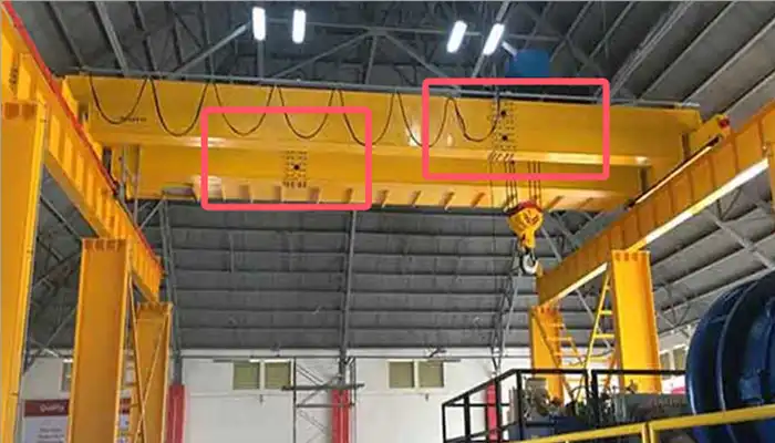
Use a Bolted Flange Connection (Field Splice Joint)
This is the most widely used, proven, and engineer-approved method for assembling segmented girders on-site.
Key Features:
- Flange Plates: Heavy-duty flange plates are factory-welded to the cut ends of each girder section. They provide a flat, rigid face for bolting.
- High-Strength Bolts: Bolts of Grade 8.8 or 10.9 (or ASTM A325/A490 equivalents) are used. These are designed for structural applications requiring high preload and shear capacity.
- Alignment Pins or Dowels: These ensure that the girder sections are perfectly aligned during assembly, preventing twisting, offset, or misalignment in camber or web.
- Web Stiffeners or Reinforcing Plates: Often added around the splice area, especially on double girder bridge cranes, to resist localized deformation and strengthen the joint.
Engineering Considerations for the Flange Connection
The design of the field splice joint must be evaluated and approved by a qualified structural or crane engineer.
Design Loads to Consider:
- Bending Moment Capacity: The flange joint must carry the same bending strength as the uncut girder section.
- Shear Forces: The bolts and web plates must resist shear forces transferred between segments.
- Axial Forces: For cranes that operate under dynamic or longitudinal loads, axial stress must also be considered.
- Fatigue Resistance: Connections must handle cyclical loading—particularly important for cranes operating at high duty cycles or in steel mills, ports, or container yards.
Welding Quality:
- Flange plates should be welded in the factory under controlled conditions to ensure consistent weld penetration and dimensional accuracy.
- Welding must conform to AWS D1.1 or equivalent standards (as applicable in your country).
Bolt Torque:
- Bolts must be tightened using specified torque values, often using torque wrenches or hydraulic bolt tensioners.
- A torque sequence (usually a cross pattern) should be followed to ensure even load distribution and joint clamping force.
On-Site Assembly Procedure
Connecting segmented girders on-site requires proper tools, lifting equipment, and trained personnel. The general steps are as follows:
Step-by-Step Process:
- Support Both Girder Sections: Place both girder segments on level assembly stands or temporary supports. Ensure they are well-secured before alignment.
- Align the Ends: Use hydraulic jacks, chain blocks, or alignment tools to bring the flange plates into position. Guide pins or dowels help ensure precision.
- Insert Bolts: Install all bolts loosely at first, using a diagonal or cross pattern to maintain even clamping forces across the flange.
- Tighten Bolts Gradually: Apply torque in multiple passes, gradually increasing until the specified torque value is achieved.
- Check Alignment: Measure and verify the camber, straightness, web plumbness, and flange levelness. Corrections must be made before final torquing.
- Final Torque Check and Inspection: Re-check bolt torques after 24 hours (or after initial load application), and conduct visual inspection for bolt seating, flange gap, or defects.
Optional: Internal Sleeve or Box Insert for Enhanced Strength
In some high-capacity or fatigue-sensitive cranes, an internal sleeve (also called a splice box or insert box) is used.
Purpose and Benefits:
- The sleeve fits inside the girder web and partially into both segments.
- It helps align the two girder sections internally and distributes stress away from the flange bolts.
- Offers added torsional rigidity and resists out-of-plane deformation during crane operation.
This method is often used in:
- Port container gantry cranes
- Very long-span double girder cranes
- Cranes subject to high dynamic or seismic forces
Precautions and Best Practices
To ensure safety, durability, and compliance with engineering standards:
- Never perform field welding of structural connections unless pre-approved by a qualified engineer and conducted under controlled conditions.
- Always use the specified bolt grade, torque values, and assembly sequence. Substituting components can result in unsafe joints.
- For top-running cranes, check and align the crane rail or track across the girder splice to prevent trolley derailment or uneven wear.
- Perform a load test after final installation—typically at 125% of rated capacity—as per ISO, CMAA, or GB standards, to confirm splice strength and performance.
Related:Crane Girder Designs:Single vs Double Girder, Beam & Box Girder. Contact us to get your customized girder crane, single girder crane and double girder crane!
Article by Bella ,who has been in the hoist and crane field since 2016. Bella provides overhead crane & gantry crane consultation services for clients who need a customized overhead travelling crane solution.Contact her to get free consultation.