3 Layers Sandwich Plate Girder Connection for 15-Ton EOT Cranes
Step-by-Step Guide to Reliable Sandwich Plate Girder Connections for 15Ton Bridge Crane Ensuring Strength & Easy Installation. Get long span eot crane!
| Application | Material handling, lifting, positioning, assembly, maintenance, loading/unloading, |
| Certifications | CE / ISO / SGS / Other third-party inspection |
| Customization | Customized material handling cranes solutions available for indoor, outdoor, hazardous, corrosive, cleanroom, and heavy-duty industrial applications. |
Category: Featured
Tags: 15ton
Your Trusted Overhead Bridge Crane Manufacturer & Supplier
Reliable 3 Layer Girder Connection 15-Ton Bridge Crane Case
Step-by-Step Sandwich Plate Guide
How the 15-Ton Bridge Crane Girder Is Split and Connected
When dealing with a 15-ton bridge crane with a span of 13,132 mm, transporting the main girder as a single piece may not be feasible. In such cases, it's common practice to divide the girder into two sections—in this case, 7,908 mm + 5,292 mm—for easier shipping and site handling. But once split, the challenge becomes: how do you securely reconnect these sections so that they perform like a single, continuous girder?
That's where the "sandwich plate" method comes in. It's a simple, proven solution that's both strong and practical.
Why Use the Sandwich Plate Method?
The sandwich plate method reinforces the joint between the two girder sections by clamping them between two thick steel plates—just like a sandwich. This method is commonly used in medium-capacity cranes like 10-ton, 15-ton, and even 20-ton bridge cranes where girder length makes transport tricky but structural integrity is non-negotiable.
Key Advantages:
- Safe and sturdy – Restores original girder strength with proper bolt tensioning
- Quick installation – No need for on-site welding
- Easy alignment – Factory pre-drilled holes ensure precise assembly
- Transport-friendly – Allows girder sections to fit standard container lengths
Practical Tips for a Smooth Girder Connection
Getting the connection right the first time saves hours—maybe days—of future adjustments. Here are a few on-site tips to help:
- Pre-assemble in your workshop if possible – this helps identify any issues with hole misalignment early
- Use high-strength bolts (Grade 8.8 or higher) – standard bolts won't do the job
- Mark the girder sections during production – to avoid confusion during site assembly
- Add anti-corrosion coating on the inner side of the plates – especially if the crane is used outdoors
This sandwich-plate method offers a strong, straightforward solution for connecting split girders. If done correctly, the joint won't affect the load capacity or deflection performance of your 15-ton bridge crane. Always follow the supplier's assembly instructions—and if in doubt, ask for an on-site supervisor for the initial installation.
Why Use a Two-Section Girder?
When designing and installing a 15-ton overhead crane with a span of 13,132 mm, using a girder in two sections — one 7,908 mm and the other 5,292 mm — isn't just an option. In many real-world projects, it's a practical necessity. Here's why this approach works better, especially in industrial projects outside the factory setting.

Transport Limitations: Getting the Beam to Site Without Trouble
Transporting a single-piece girder over 13 meters long can be a major headache. In many countries, this length exceeds standard container sizes or trucking limits. You might need special permits or escort vehicles, which means added time, cost, and paperwork.
- Container fit: A 40-foot container handles up to around 12 meters, so a 13.1-meter girder won't fit.
- Truck limitations: Oversized loads may need road permits or limited travel times, especially in cities or on highways.
- Safety concerns: Longer beams are more prone to flexing or damage during transport if not supported correctly.
By splitting the girder into two sections, each part becomes much easier and safer to ship. No need to pay for oversized transportation or worry about bending during the trip.
Easier Handling on Site: Smooth Lifting and Installation
Big sites aren't always open and spacious. In many plants or workshops, cranes are installed after part of the building is already in place. Trying to maneuver a full-length beam into position inside a nearly finished structure is risky and time-consuming.
- Shorter lengths are lighter and easier to hoist.
- Alignment of segments is more manageable in tight spaces.
- Lower lifting height reduces crane or hoist size needed during installation.
This modular approach makes sense when you don't have large mobile cranes on-site or the building restricts access.
Standardization from the Factory: Precision and Efficiency
Most manufacturers now design long-span bridge cranes with jointed girders as a standard offering — not just a customization. These connection sections are CNC machined and prepared in advance for accurate field assembly.
- Precise end faces and bolt holes for easy matching.
- Factory pre-drilled plates to reduce site welding.
- Quality control done before shipment to reduce on-site issues.
The benefit is clear: less field work, faster installation, and a better fit
The Sandwich Plate Connection Method
When you're dealing with a split main girder—like in a 15-ton overhead crane with a 13.132-meter span—how those two beam sections come together is critical. One of the most effective and commonly used methods in this case is the sandwich plate connection.
What Is a Sandwich Plate Connection?
This is a mechanical connection approach where the top and bottom flange plates of the main girder are securely clamped between two thick steel splice plates. Think of it like pressing the beam flanges between two steel "buns"—hence the sandwich analogy.
- The girder web, which is the vertical center plate of the beam, sits in the middle.
- The outer splice plates go on the outside of the top and bottom flanges.
- High-strength bolts are inserted through all the layers to hold everything together.
- Final assembly looks like this: Splice Plate – Girder – Splice Plate.

This method is commonly used in overhead crane design when beams are made in multiple sections for transport or fabrication reasons.
Components in the Connection:
Here's what's included in a typical sandwich plate joint for a 15-ton crane girder:
- 2 Outer Splice Plates (top and bottom): These are thick steel plates pre-drilled with bolt holes, designed to match the shape and thickness of the girder's flange plates.
- 1 Girder Web: The vertical plate that makes up the center of the main beam.
- High-Strength Bolts (e.g., M24 or M30) : Bolts pass through the splice plates and girder body, tightened to torque specs for maximum clamping force.
Why This Method Works So Well
The sandwich plate method isn't just simple—it's highly effective for industrial use:
- Efficient Load Transfer
Forces move smoothly from one girder section to the next without deformation or slippage. - Excellent Shear and Bending Resistance
The wide plate area and bolt positioning give the joint good performance under vertical loads and twisting forces. - Easy to Inspect and Maintain
All bolts and plates are visible from the outside. You can retighten bolts or replace parts if needed, without cutting or welding.
Practical Notes for Buyers and Installers:
- Make sure your beam flanges and splice plates are machined flat and pre-drilled in the factory—that ensures tight contact and easier alignment.
- Always use torque wrenches to tighten bolts to the specified levels.
- For outdoor cranes, consider galvanized bolts or anti-corrosion treatment for the connection plates.
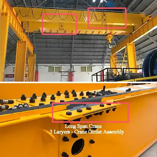
Reliable 3 Layer Girder Connection 15-Ton Bridge Crane
The Connection Assembly Process – Step by Step
Connecting the two girder sections on-site using the sandwich plate method might sound straightforward, but careful attention to each step ensures a strong, durable, and safe joint. Here's a detailed walkthrough to help installers and project managers get it right the first time
Step 1: Preparation
Before you start assembling, make sure everything is clean, organized, and properly supported.
- Place the two girder sections (7,908 mm and 5,292 mm) on level alignment jigs or sturdy supports. This keeps the beams stable and at the right height for assembly.
- Clean all contact surfaces thoroughly. Remove dust, grease, rust, or any debris that might interfere with a tight fit between plates.
- Inspect bolt holes carefully. Check that all holes in the girder ends and the connecting plates line up perfectly. Any misalignment here can cause serious issues later.
- Verify overall alignment. Before moving forward, do a rough check to see if the two beam ends naturally sit flush. If not, plan to make adjustments during assembly.
Step 2: Sandwich Plate Positioning
Now comes the core of the method—placing the connecting plates correctly around the girder ends.
- Slide the top and bottom connecting plates over the girder flanges, sandwiching the beam ends. It's crucial that these plates fit snugly against the flange surfaces.
- Check bolt hole alignment again. All bolt holes in the connecting plates and the girder must line up exactly.
- Ensure the plates sit flat without gaps. Gaps can reduce load transfer efficiency and cause uneven bolt stress.
- If necessary, use light tapping or hydraulic tools to gently nudge the plates into perfect position.
Step 3: Bolt Installation
With plates in position, it's time to fasten the joint securely.
- Insert the high-strength bolts through the aligned holes. Typically, these will be Grade 8.8 or 10.9 bolts designed for heavy structural loads.
- Hand-tighten all bolts initially. This keeps the plates in place while allowing minor adjustments.
- Tighten bolts in a cross or star pattern. This method ensures even pressure distribution across the connection.
- Use a calibrated torque wrench to reach the manufacturer's specified torque value for each bolt. Proper torque is key to prevent bolt loosening or joint slipping under load.
- Apply torque gradually, usually in multiple passes. Don't fully tighten bolts on the first try; instead, tighten a bit, then go back and repeat until final torque is reached.
Step 4: Alignment and Leveling
Once bolted, the girder joint needs a final alignment check to ensure proper crane operation later.
- Measure girder straightness and camber at the splice. The goal is to keep deviations within allowable limits to avoid trolley misalignment or uneven wear.
- Check vertical and horizontal deflection tolerances. Make sure the joined beam behaves like a continuous member.
- Make fine adjustments as needed. This may involve loosening bolts slightly and shifting plates or girder sections before re-torquing.
Step 5: Final Inspection
Before considering the connection complete, a thorough inspection is essential.
- Verify all bolts are torqued to spec. Use a torque wrench to re-check every bolt.
- Inspect the surface contact of the splice plates and girder flanges. Ensure no visible gaps, cracks, or distortions.
- Mark bolt heads with paint or a torque seal. This provides a quick visual check to know bolts haven't loosened later.
- Document the assembly process. Record torque values, inspection results, and any adjustments made for future reference.
Technical Notes & Tolerances
When connecting crane girders with the sandwich plate method, paying close attention to technical details and tolerances ensures the joint performs safely and lasts long. Here are some important points to keep in mind
Bolt Grade and Quality
- Always use Grade 10.9 or higher high-strength bolts for the splice connection. These bolts are specifically designed to withstand heavy shear and tensile forces that overhead crane girders experience.
- Using lower-grade bolts might save money initially but risks joint failure, increased maintenance, and safety hazards.
- Make sure bolts comply with relevant standards such as ISO 898-1 or equivalent national standards.
Torque Standards and Procedures
- Follow national or international torque standards, such as ISO 16047 or CMAA recommendations for overhead cranes.
- Proper torque ensures the bolts are tightened enough to develop full clamping force but not so tight as to risk thread damage or bolt snapping.
- Use a calibrated torque wrench or hydraulic tensioners to apply consistent and repeatable torque values.
- Always tighten bolts in the specified sequence, usually a cross or star pattern, to distribute pressure evenly
Flatness and Alignment Tolerances
- The maximum allowable gap between the sandwich plates and the girder flange should be 0.5 mm or less. Larger gaps reduce load transfer efficiency and may cause localized stress concentrations.
- Surfaces must be flat and clean to maintain full contact and avoid bending or twisting at the splice.
- If the gap exceeds tolerance, machining or surface grinding may be necessary before assembly
Welding Restrictions
- The splice joint should not be welded on-site. Welding can cause distortion, residual stresses, and potential weakening of the girder ends.
- All welding related to the girder should be completed at the factory under controlled conditions, before delivery.
- The connection relies on mechanical fastening via bolts, which also simplifies future inspections and maintenance.
Common Applications of Split Girder Cranes
The practice of splitting crane girders and reconnecting them onsite with sandwich plate joints is common across many industries and scenarios. Here are some typical examples where this approach shines:
Workshop Retrofits and Plant Upgrades
- Many factories upgrading existing facilities have limited access points, narrow doorways, or low ceilings.
- Bringing in a full-length girder isn't practical, so splitting the beam allows smooth transport and easy assembly inside the building.
- This approach minimizes downtime and disruption to ongoing operations.
Exported Cranes Shipped in Containers
- Overseas shipment of overhead cranes almost always requires girder segmentation.
- Container sizes and shipping costs encourage breaking down long girders into sections that fit standard containers or flat racks.
- On-site assembly using sandwich plate connections makes rejoining these sections straightforward and reliable.
Pre-Assembled Modular Crane Structures
- Some crane manufacturers provide modular crane kits with split girders ready for fast field assembly.
- This modular approach supports faster construction schedules and easier customization.
- It's ideal for projects where cranes must be installed quickly or in challenging site conditions.
Conclusion
Using the sandwich plate connection method to join split girders in 15-ton overhead cranes is a reliable and well-established practice in the crane industry. It has been proven over countless projects worldwide to deliver strong, safe, and durable joints that meet or even exceed the performance of single-piece girders.
This connection method maintains the structural integrity of the crane's main girder, ensuring it can handle bending, shear, and dynamic loads just as effectively as a one-piece beam. When properly designed, fabricated, and assembled, the joint behaves like a continuous beam under all typical operating conditions.
Beyond strength, this method is highly practical and flexible. It solves many common challenges faced by crane buyers and installers, especially when:
- Transporting very long girders is impossible or prohibitively expensive due to road or shipping constraints.
- Installation sites have limited access, tight spaces, or overhead restrictions that make handling large, heavy beams difficult.
- Fast on-site assembly is required to minimize plant downtime or meet tight project schedules.
For these reasons, splitting the main girder into two sections connected by sandwich plates offers a smart balance between engineering performance and logistical convenience. It's a cost-effective, safe, and efficient solution that supports modern crane manufacturing and installation needs.
If your project involves a 15-ton bridge crane with a large span, or if you anticipate challenges with transportation or site access, discussing a split girder design with your crane supplier can save you time, cost, and hassle. And with proper attention to assembly details—like bolt grade, torque, and alignment—you'll get a crane girder joint that's built to last.


Free consultation to Confirm Parameters & Specifications and Get
Latest Crane Price & Crane Rate.
- Types of overhead cranes : _______?
- Optional: Overhead travelling crane, goliath gantry crane,Slewing jib crane, Single girder or double girder crane,small portable crane or kbk crane, etc.
- Capacity of overhead crane: _______?
- Optional: 0.25ton, 0.5 ton, 1 ton, 2 ton, 3ton, 5 ton, 10 ton,15ton, 20ton, 25 ton, 30ton,35ton, up to 550ton, etc.
- Crane span & lifting height : _______?
- Crane travelling length : _____?
- Control of overhead crane:_______?
- Optional: pendant/ remote/cabin control
- Voltage supply of overhead crane:_____?
- Eg,: 380V50/60HZ,3Phase or others,etc.
- Application/usage of crane:_______?
- Eg,: Steel mill, ,injection mold, cement,stone, concrete,granite, general manufacturing, etc.
Just leave a message via the contact form and our hoist and crane engineer will contact you with in 24working hours.
Get In Touch