Electrification & Power Supply of Electric Overhead Crane
Content Quick Link
Electric overhead cranes basics on crane, bridge & runway electrification, power supply systems, electric motors & Controllers, electrical grounding, etc.
Electric overhead crane is one of the main type of overhead travelling crane. The electric overhead crane is the most frequently used material handling , compared with the manual crane, and air hoist.
In the following section, we will discuss the following:
- Types & Features of Electric Overhead Cranes
- Methods of Overhead Crane Electrification
- Bridge and Runway Electrification
- Electric power supply - Festoon Systems
- Electric Motors and Controllers
- Electrical Grounding
Electric overhead cranes are commonly used in manufacturing, warehousing, repair, and machinery maintenance , mold handling or other loads handling to increase working efficiency and safety while also streamlining your work flow. These overhead cranes can be electronically controlled by using a control pendant, a wireless remote, or a cabin control. To fit different working environments and lifting needs, electric overhead travelling cranes are available in four basic configurations: single girder, double girder, top running, and underhung system.
Types of electric overhead cranes
Single girder electric overhead crane – The single beam supports an electric hoist that runs along the bridge beam's bottom flange. Single girder electric cranes, with capacities ranging from 1 ton to 20 tons, are commonly used for light duty to moderate duty applications. These eot cranes are typically less expensive due to their simple hoist and trolley design, lower freight costs, and faster installation.
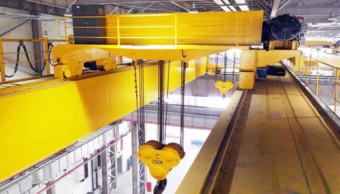
Double girder electric overhead crane: There are two bridge girders setting on the top of the end trucks. With the crane placed between the two girders, the electric bridge cranes be installed a top running trolley and hoist to increased lifting height. Double girder cranes are designed for heavier-duty applications and can be used for material handling from 3 ton to 320 ton, or more.

Single Girder Electric Overhead Crane
Single girder electric overhead crane parameters:
- Load capacity: 1-25t
- Span: 7.5-31.5m
- Lifting height: 6-30m
- Lifting speed: 0.3-8m/min
- Hoist running speed: 20m/min
- Crane running speed: 20m/min
- Work duty: A3, A4

Electric Double Girder Overhead Crane
Double girder electric overhead travelling crane parameters:
- Load capacity: 5-450t
- Span: 10.5-31.5m
- Lifting height: 6-24m
- Lifting speed: 2.1-11.5m/min
- Trolley running speed: 27-40m/min
- Crane running speed: 42-75m/min
- Work duty: A3-A7
Top running electric overhead crane: The bridge girder travels on top of rails mounted on the runway beam. These top running cranes are the most common type of crane design and can handle extremely heavy loads. Top- running electric overhead cranes also provide maximum lifting height as well as reliable and long-lasting performance.
Underhung or under running overhead crane: This electrical crane can lift up to ten tons. It is supported by the roof structure of the building and runs on the bottom flanges of the runway beams. Underslung bridge cranes provide excellent side approach, maximizing building width and height utilization. The light electirc cranes also eliminate the need for building columns or support columns, resulting in significant material savings.
Overhead Crane Electrification
Most hoist electrification systems have two circuits: a power circuit and a control circuit.
- Power Circuit - The power circuit supplies the energy needed by the electric crane to lift and move heavy objects and power other electric motors. Bridges, trolleys, and hoists must be powered by proper sources because they move during operation.
- Control Circuit - Another secondary low voltage electrical circuit that powers the control mechanisms is the control circuit. The electric overhead crane or hoist is often operated by a push-button pendant that the operator holds in their hand. It makes sense that lowering voltage and current would reduce the risk of shock.
Methods of Overhead Crane Electrification
Overhead crane electrification is commonly accomplished through two methods: 1) insulated power bar / busbar and 2) electric festooning system.
- Insulated power busbars - When compared to other power systems, this method uses insulated bars with a sliding shoe collector system, which eliminates most of the exposed conductor safety hazards and provides a very high amperage option. Although this method is superior to others, the shoes wear out quickly.
- Festoon - A trolley traveling on a C rail with a flat cable provides direct contact that is extremely wear resistant. It has the advantage of greater reliability; however, it is not recommended for curved rails.
At the moment, insulated crane bus bar is the preferred option for crane runway electrification, while festooning is the preferred option for bridge cross conductors and floating pushbuttons. When multiple independently moving systems must operate on the same runway or bridge, routing electric crane festoon systems becomes somewhat difficult. When two or more bridges frequently operate on the same runway system, using the insulated bar for runways makes sense.
Crane Bridge and Runway Electrification
The diagram below depicts a basic insulated power bar configuration for the crane runway:

Electric conductor bar - single pole conductor bar
The runway electrification power supply is made up of a series of insulated bars/ busbar made of galvanized steel, copper, stainless steel, or aluminum that transmit electricity through sliding collector assemblies that power the motors, travelling trolleys, and electric hoists, etc.
1. Conductor Bars -Track electrification must be accomplished through the use of a UL-approved conductor continuous bar.- Conductor bars must be one piece copper conductors with thermoplastic insulating covers and end covers. Due to the fact that the insulated bar, when viewed from the end, resembles a figure 8, the insulated bars are also known as "8-bar systems." To ensure positive electrical contact between the collectors and the conductors, the conductors must be precisely aligned. For each phase, separate conductors must be provided; it is also forbidden to house more than one conductor in a single enclosure.
- The maximum voltage drop for the track electrification system from the building's power takeoff point to the hoist motor is 4%. In order to keep the overall voltage drop in the conductors while the current flowing through each individual motor is operating at full load to a maximum of 3% of the supply voltage, bridge conductors must be sized proportionately.
- The conductors' short-circuit current rating must be at least 10,000 amperes.
- The thermal rating of conductors for continuous current shall not be greater than 140°F (60°C) based on an ambient temperature of 86°F (30°C).
- The incoming power circuit must include a fused manual disconnect switch with a lockable handle located through the panel door.
- All power for the electric overhead crane must come from a single main visible blade fuse switch that is conveniently situated on the crane bridge.
A current collector assembly must be self-centering and able to work through splices, gaps, and switches. For systems utilizing galvanized steel conductors, it must have extension sections every 150 feet (45,720 mm), and every 100 feet (30,480 mm) for systems using copper conductors.
4. Hangers and supports -Bars are fastened to brackets that are frequently either laterally mounted, web mounted (for top running cranes), or fixed to a flange (for monorails or under-hung cranes).
5. End covers -used to cover the conductors' exposed ends to prevent unintentional contact.
6. Insulating covers - Insulating covers have a thermal distortion point of 160°F at 260 pressure and are made of stiff PVC.
7.Connector pins—Used to connect the conductor bar sections
The system must include all necessary components, including disconnect switches, conduits, and wiring to the power takeoff point. These components also include unit length conductors, insulating conductor covers, insulators, splices and splice covers, end caps, support brackets and fasteners, current collectors, expansion, isolation, and power-interrupting sections.
Typical Installation Guidelines
In order to properly select a bar system, it is necessary to determine the following:
- It is vital to ascertain the following in order to choose a bar system properly:
- The System Type (monorail, runway, bridge)
- Duration of Run
- Amount of Cranes and Current Needs
- The quantity of conductors (calculate an extra for ground)
- Location of the Power Supply
- Input Voltage
- Condition and Duty Cycle
- ·Environment
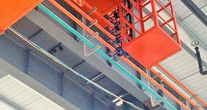
Festoon Systems
Festoon Systems fall under the C-Track or Tagline (wire) design categories. A runway, hoisting trolley, electric bridge crane auxiliaries, or lower voltage control to a different pendant station circuit are all powered by C-Track Festoons. Although spherical versions are also available, the Festoon Cable is normally flat.
The advantages of a flat cable over a round cable are that the flat cable will stack up without twisting and that numerous layers of cable can fit on a single trolley. Tagline Festoons are typically used to power and regulate hoist systems or smaller cranes.

C-Track Festoon System
The following are typical requirements for a festooned bridge conductor system:
Extra-flexible stranded copper conductors and cross-linked 90°C polyethylene insulation rated 1000V with a high temperature outer jacket must be used in festooned bridge conductor systems. The manufacturer of the hoist and trolley must be consulted for the suggested conductor sizes.
In order to give safe access to the cables and catenary system, a rail-type cable support system known as "messenger track" must be erected above one of the main bridge platforms. From the bridge to the trolley or from the bridge to a pendant control unit, current can be sent using the festooned wires.
Electric Motors and Controls
The electric overhead cranes need powered motors in three places, depending on the application:
- Motors for bridge and end trucks
- Trolley motors
- Hoist motors
Motor Specifications
One of the crucial considerations in the choice and use of electric crane motors for overhead travelling crane operations is the duty cycle given to the motor, which determines how frequently and for how long a motor operates. The duty cycle, starting, temperature, and operating environment are important factors in the reliability and efficiency of the motor. It is vitally essential to match the motors to their specified operating conditions for minimizing strains on the motors and to acquire intended performance and life.
A traveling electrical crane uses both AC and DC drives for its various operations. Below is a list of the preferred drives when considering economy and utility:
Operation | Type of drive |
Hoisting and lowering | AC slip ring motor, controlled DC shunt motor and DC compound motor. |
Crane travel | AC slip ring motor. |
Trolley travel | AC slip ring motor. |
Slew and swing action | AC slip ring motor or DC shunt motor. |
Boom hoist | AC slip ring motor. |
Slip-ring electric crane motors are useful:
- 1.When very fine speed control is necessary, such as while a crane must be positioned above a furnace opening or when handling loads slowly and quickly during hoisting and lowering.
- 2.If the loading conditions are not uniform, a number of sequences must be used to complete the process.
- 3. In situations when cranes must start and reverse numerous times while in use.
- 4. In situations when the cranes must have a starting torque that is generally more than 2.5 times the rated torque.
In applications like cranes used in steel mills, power plants, and concrete dams, where smooth, precise, and quick speed control are necessary, DC motors are employed for lifting and lowering loads.
Squirrel Cage Motors may also be used for various electric overhead crane uses: :
- 1. When the driving equipment must accelerate quickly under constant load conditions and a predetermined operation sequence, such as using a mechanical workshop crane.
- 2. When the load conditions are nearly same in both rotational directions, such as during long or transverse travel of a gantry crane.
- 3. If the electric overhead cranes have no speed control and only run at one pace.
- 4. If the site has corrosive or dusty conditions, these motors with fully enclosed fan cooling systems would be durable and offer services with the least amount of maintenance.
- 5.The price must be taken into account, as a cage motor is less expensive than a slip-ring motor.
Selection Criteria
Due to the requirement of handling materials of various weights, the ability to work under different load conditions, speed control, sequential switching, and suitability to swiftly reverse are the most crucial and fundamental technical aspects for the selection of a motor for a electric powered crane service (i.e. loads).
1.Speed control - This is a crucial component of electric overhead crane drives. It is necessary to permit gentle beginning and halting of the travel motions in order to enable the proper load arrangement. The speed control in a broad speed range, from zero to nominal values, is necessary for the lifting drive. The ability to work at extremely low speeds and keep a load at a standstill without utilizing mechanical brakes is necessary due to the precision required when raising and lowering the weight. DC remains the ideal option. However, if the right drive and motor are used, AC systems should be able to achieve performance requirements that are comparable to those of DC SCR systems. You will base your choice on two main considerations if an AC motor is to be used.
- Heat - Heat generation is the main issue, and this heat output needs to be dissipated. For instance, a 40 HP, 2:1 gearless AC with 50% counterweighting would generate 22 KW of heat as regenerated power.
- Cost - A regenerative AC drive, which avoids the heat issue, will cost 1.5 to 2.5 times as much as a non-regenerative drive (standard flux vector drive).
2. Torque and Power - The load's high torque requirements during acceleration and starting phases are the other crucial factor to take into account. The torque versus speed characteristic of the load can be used to determine the torque and power that the drive must deliver (called mechanical characteristics). The following are typical AC drive operating qualities:
- Below full load RPM: Constant torque mode output
- Above full load RPM: Output produced in constant HP mode
This indicates that the output torque of the AC motor diminishes above the full load RPM. Therefore, a motor's Full Load RPM must be within 5% of the RPM necessary to operate the hoist at contact speed. To choose an AC motor, use full load RPM data rather than synchronous RPM data.
3.Time Delay - Be aware that AC drives have a starting delay that affects the overall performance time. In AC applications, the motor is energized (through a power contactor) only when it is needed, in contrast to DC applications where the motor field is always energized. The brake cannot be raised until enough time has passed for magnetic flux to accumulate inside the engine. Depending on the parameters of the motor, the delay time can range from 200 milliseconds to more than one second. The AC motor and drive must therefore tolerate a delay on start that does not exist with DC motors and drives, all other conditions being equal.
4. Motor Type - Drives shall be rated to handle the entire load current of the hoist motors continuously for 10 minutes. The drives must be rated to continuously carry the entire load current of the long and cross travel motors for 5 minutes. Motors must be completely enclosed, non-ventilated, certified for 30-minute time-rated operation at full identification plate power output in an environment with an ambient temperature of 104°F (40°C), a maximum temperature rise of 167°F (75°C), and insulation that meets Class B system standards. Motors for hazardous environments must be explosion resistant if stated.
Wrap it up for final selection- Wherever varying loads are to be operated, it is common to choose a motor rating based on the greatest anticipated load. However, a more efficient and cost-effective strategy is to select a motor with a rating slightly lower than the peak anticipated load and allow it to function at overload for a short amount of time, rather than selecting a motor with a high rating that would operate at full capacity for only a short period of time, offering optimum efficiency only for that short period. The thermal capacity of the motor, which controls the rate of winding insulation degradation, is the only factor to consider for motors operating at greater speeds than their specifications.
Enclosures
The National Electrical Manufacturers Association (NEMA) rates the enclosures according to the level of protection they offer from the elements outside. The enclosures hold all of the electrical parts of the crane. The standard procedure is to need NEMA 1 level of protection for all electrical equipment and NEMA 12 level of protection for all control panels.
Electtrical grounding
A safe installation must include proper grounding. Electronics like remote controls, variable frequency, electronic monitoring tools, etc. are being added to cranes on a constant basis. These require grounding for their safety.
According to NEC 610, Overhead Crane/Hoist According to Article 250, (grounding) Parts V and VII, all exposed non-current-carrying metal parts of cranes, hoists, and accessories, including pendant controls, must be connected together mechanically or with bonding jumpers, as appropriate, to create a ground-fault current path that runs through the entire crane or hoist.
For grounding reasons, moving components that aren't removable accessories or attachments with metal-to-metal bearing surfaces are deemed to be electrically linked to one another through those surfaces. The bridge and trolley wheels and their respective tracks are NOT to be regarded as electrically grounding the trolley frame and bridge frame. According to the 2005 NEC, a separate bonding conductor must be provided for grounding the trolley's wheels and the corresponding tracks (610.61).
Electrical standards
The wiring, contact conductors, controls, over-current protection, and grounding for electric overhead cranes, bridge-trolleys, runways, and electric hoists must all comply with NFPA 70. Article 610 of the National Electric Code and NEMA Publication No. ICS 8 must both be followed by all electrical equipment (Cranes and Hoists).
For either AC or DC current, the control circuit voltage cannot be higher than 600 volts. Ideal US requirements are 480 volts, three phases, and 60 hertz.
When it comes to AC and DC, the voltage at pendant pushbuttons must not be higher than 150 volts.
Related to electric overhead travelling cranes


Article by Bella ,who has been in the hoist and crane field since 2016. Bella provides overhead crane & gantry crane consultation services for clients who need a customized overhead travelling crane solution.Contact her to get free consultation.
Free consultation to Confirm Parameters & Specifications and Get
Latest Crane Price & Crane Rate.
- Types of overhead cranes : _______?
- Optional: Overhead travelling crane, goliath gantry crane,Slewing jib crane, Single girder or double girder crane,small portable crane or kbk crane, etc.
- Capacity of overhead crane: _______?
- Optional: 0.25ton, 0.5 ton, 1 ton, 2 ton, 3ton, 5 ton, 10 ton,15ton, 20ton, 25 ton, 30ton,35ton, up to 550ton, etc.
- Crane span & lifting height : _______?
- Crane travelling length : _____?
- Control of overhead crane:_______?
- Optional: pendant/ remote/cabin control
- Voltage supply of overhead crane:_____?
- Eg,: 380V50/60HZ,3Phase or others,etc.
- Application/usage of crane:_______?
- Eg,: Steel mill, ,injection mold, cement,stone, concrete,granite, general manufacturing, etc.
Just leave a message via the contact form and our hoist and crane engineer will contact you with in 24working hours.
Get In Touch