How to Prepare Rebar Mill Crane Specifications for Steel Plant EPC Tender Documents
Content Quick Link
Key Takeaway: A Rebar Mill Crane Specification Must Match the Whole Steel Production Process
A crane specification for a rebar mill EPC project is not only a list of lifting capacity and dimensions. It is a technical document that connects steel production process, factory layout, material handling requirements, building structure, electrical system, and future maintenance work.
Many EPC contractors face the same situation. The rolling mill equipment is selected first. The crane comes later. Then problems appear.
- The crane cannot reach some maintenance areas.
- The runway beam needs reinforcement after construction.
- The lifting height is too low for equipment replacement.
- The selected crane duty class cannot handle continuous operation.
- The electrical system does not match the plant power supply.
A well-prepared rebar mill crane specification should be completed during the EPC engineering stage. The main information should include mechanical data, electrical requirements, installation conditions, working environment, and safety requirements.
The goal is simple: the crane should fit the factory before it arrives at the site.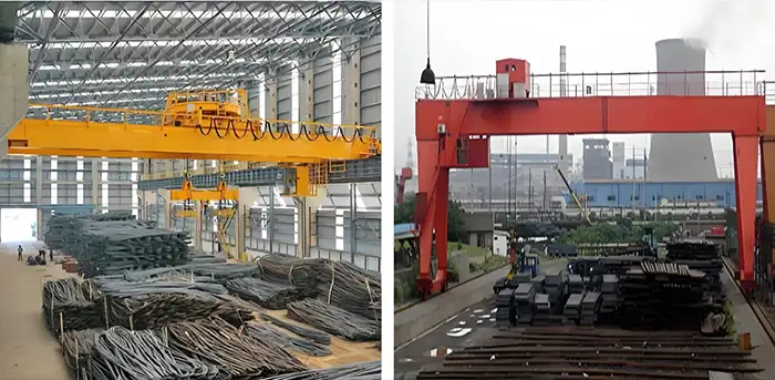
Role of Overhead Cranes in a Rebar Mill Production Line
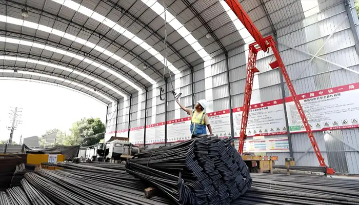
A rebar mill is a continuous steel production system. Steel billets enter the plant. They move through raw material storage, reheating furnace, rolling mill, cooling bed, finishing area, and finished product storage.
During this process, overhead cranes support daily material handling and maintenance work.
| Area | Crane Application |
|---|---|
| Billet storage yard | Steel billet lifting, stacking, and transportation |
| Furnace area | Billet loading support and maintenance handling |
| Rolling mill area | Roll change, motor lifting, equipment maintenance |
| Finishing line | Rebar bundle movement |
| Workshop | Machine repair and spare parts handling |
| Warehouse | Loading and unloading materials |
How to Define Rebar Mill Crane Specification During EPC Design
Defining the right overhead crane for a steel rebar mill goes far beyond just knowing the lifting capacity. During the EPC (Engineering, Procurement, and Construction) phase, a well-specified crane is the backbone of operational efficiency. In this guide, we answer the essential engineering questions that ensure your crane supports material flow, maintenance, and long-term plant reliability.
1. What Will the Crane Lift? (Understanding Lifting Purpose & Load Capacity)
Before selecting a crane, you must identify every load it will encounter. This is the fundamental question that determines crane type, lifting accessories, and rated capacity. In a typical rebar mill, the crane handles steel billets from the storage yard to the furnace, finished rebar bundles after rolling, and heavy components like motors, gearboxes, and rolling mill stands during maintenance. Often, cranes used for daily production require a different duty classification than those used occasionally for heavy overhauls. Key takeaway: Always map out the complete material flow—from raw material handling to finished product storage—to ensure your crane's load capacity supports all operational scenarios.
2. How Often Will the Crane Work? (Duty Classification & Working Frequency)
It is a common mistake to select a crane based solely on its maximum lifting weight. The working frequency and operating cycle are critical for reliability and safety. You need to evaluate the number of lifts per shift, continuous production demands, peak production schedules, and maintenance lifting frequency. For instance, a crane operating continuously in the steel production area will need a higher duty classification (e.g., FEM or ISO standards) to ensure component longevity and reduce downtime. In simple terms, a crane for daily heavy use must be built with stronger mechanical and electrical components to handle the operating cycle and prevent premature fatigue.
3. Where Will the Crane Operate? (Environmental Factors & Protection Level)
The working environment is a major factor in crane design and component selection. In a rebar mill, conditions vary widely from indoor production workshops to outdoor storage yards, high-temperature zones near furnaces, and dusty environments with mill scale and steel particles. These conditions dictate the crane protection level, motor insulation class, electrical enclosure design, and even the need for special lifting attachments. Cranes operating in harsh dusty environments or high-heat areas require extra protection against corrosion and heat to ensure equipment reliability and safety. Ignoring the environment leads to rapid wear and costly component failures.
4. How Does Material Flow Impact EPC Crane Specifications?
During the EPC design phase, the crane cannot be specified in isolation. It must be designed according to the complete material flow and production process. This means analyzing the annual production capacity, the plant layout, and the specific crane operating areas. For example, if the material flow involves frequent shifting of billets, the crane's operating configuration must ensure fast and precise movement. Engineers must collect and verify key project data, including production targets and the process flow, to size the crane appropriately and prevent bottlenecks in the rolling mill production line.
5. What Maintenance Scenarios Affect Crane Specification?
One of the most overlooked aspects in crane specification is the maintenance requirement for the rolling mill equipment itself. The crane will be used to lift and replace heavy components like rolling stands, motors, and gearboxes during scheduled maintenance and unplanned shutdowns. This requires the crane to have adequate capacity and access to all machinery areas. For example, a maintenance crane might be used less frequently, but it needs to handle much heavier and bulkier loads than daily production cranes. The specification must consider both the lifting operation during normal production and these critical heavy-lift maintenance events.
6. How Does Workshop Structure & Runway Design Constrain Crane Selection?
Workshop structure and runway design are fundamental to crane feasibility. The crane dimensions, wheel loads, and clearance heights must match the available installation space. EPC engineers must consider the plant layout and the strength of the supporting structures before finalizing the crane's span and capacity. An ill-fitting crane can lead to costly structural modifications. Therefore, a comprehensive engineering analysis is crucial to ensure the crane system is optimized for the existing building constraints and future expansion plans.
7. Duty Classification vs. Max Load: Which is More Important?
While the maximum lifting load is a crucial figure, the duty classification is often more important for long-term reliability. The duty class defines the crane's ability to handle a specific number of work cycles at a given load. For instance, two cranes might both have a 20-ton capacity, but one might be rated for light (A1-A3) duty and the other for heavy (A6-A8) duty. The heavy-duty crane will feature more robust structural components, better motors, and more advanced control systems to handle continuous operation. Matching the duty class to the working frequency ensures the crane's lifecycle matches the steel mill's production demands.
8. What Special Features Are Needed for High-Temperature Crane Operation?
Operating cranes near furnaces or rolling lines exposes them to extreme high-temperature conditions. Standard electrical components can fail under thermal stress. In these zones, engineers must specify cranes with heat-resistant motor insulation, specialized electrical enclosures for heat dissipation, and thermal protection for the control system. Additionally, the control system configuration must be designed to allow operators to work safely from a distance. Using special lifting attachments designed for hot materials is also essential for operational efficiency and crew safety.
9. How Does Crane Specification Support the Plant's Entire Lifecycle?
A reliable rebar mill crane specification is not a simple list of dimensions and capacities; it is the result of a deep engineering analysis that considers production requirements, material flow, and maintenance scenarios. The goal is to support the steel mill lifecycle—from initial commissioning through peak production to future upgrades. By defining the crane based on actual plant operation, including both daily production loads and future maintenance requirements, EPC engineers ensure the crane system remains a valuable asset for decades, reducing downtime and total cost of ownership.
10. What Key Data Must EPC Tender Documents Include for Cranes?
Before preparing the EPC tender document, engineers must collect and verify critical project information. This includes the annual production capacity and material flow requirements, detailed plant layout and crane operating areas, the complete steel billet and rebar handling process, maximum lifting loads for both production and maintenance, crane working frequency, and the maintenance requirements for rolling mill equipment. The tender must also address the workshop structure, runway design, and available installation space to ensure accurate bids and a seamless installation process.
Mechanical Data Required for Rebar Mill Overhead Crane Design
Mechanical data defines the lifting performance, structural design, and service capability of a crane. For an EPC steel plant project, the crane specification should be prepared based on actual production requirements, maintenance scenarios, and future operating conditions.
Before finalizing the crane technical specification, EPC engineers should define the following mechanical design inputs:
| Mechanical Data | Typical Specification | Design Purpose |
|---|---|---|
| Crane Capacity | 5 ton - 100+ ton | Determine main structure, hoisting mechanism, and safety requirements |
| Crane Span | 10 m - 35 m (typical steel workshop range) | Match building width and production equipment layout |
| Lifting Height | 6 m - 20 m+ | Ensure safe material handling and equipment maintenance clearance |
| Working Duty | FEM 2M - 5M / ISO M5 - M8 | Define fatigue life and component selection |
| Travel Distance | According to workshop length | Determine runway system and power supply arrangement |
| Operating Environment | Indoor, outdoor, high temperature, dusty area | Select protection level and special components |
Crane Capacity Selection
Crane capacity is usually the first item defined in the EPC technical specification. It represents the maximum safe lifting load of the crane under designed operating conditions.
However, selecting crane capacity only according to daily production material is a common mistake. For rebar mills, engineers should evaluate both production handling loads and future maintenance loads throughout the plant lifecycle.
Typical crane capacity ranges in rebar mills depend on the application area:
| Application Area | Typical Crane Capacity |
|---|---|
| Maintenance workshop | 5-20 Ton |
| Finished rebar bundle handling | 5-30 Ton |
| Rolling mill maintenance crane | 20-50 Ton |
| Billet handling crane | 30-100 Ton+ |
A rolling mill may normally handle steel billets and rebar bundles during daily operation. However, after several years of operation, major components may require replacement, including:
- Main drive motors
- Gearboxes
- Rolling mill stands
- Roll assemblies
- Hydraulic cylinders
- Cooling system components
Typical maintenance lifting loads may be significantly higher than normal production loads. For example:
| Equipment | Typical Maintenance Weight Reference |
|---|---|
| Rolling mill motor | 2-30 Ton |
| Gearbox | 3-50 Ton |
| Roll assembly | 5-40 Ton |
| Hydraulic cylinder | 1-15 Ton |
The crane capacity calculation should consider the total suspended load, including:
- Hook block weight (normally 5%-15% of rated capacity depending on crane design)
- Magnet weight
- Coil clamp weight
- Lifting beam weight
- Special lifting tools
- Maintenance lifting attachments
For example, a crane designed for 20 Ton equipment lifting may require a higher rated capacity if the lifting beam and attachments add several tons of additional suspended weight.
A reliable EPC specification should define the maximum lifting scenario, not only the normal production condition.
Crane Span and Factory Layout Coordination
The crane span is the center distance between the two runway rails. It determines the effective working coverage inside the workshop and directly affects material flow and maintenance accessibility.
Typical overhead crane spans in rebar production buildings are:
| Workshop Type | Typical Crane Span |
|---|---|
| Maintenance workshop | 10-20 m |
| Production workshop | 20-35 m |
| Large steel plant bay | 35 m+ |
For rebar production plants, crane span selection should be coordinated with:
- Rolling mill equipment arrangement
- Billet storage area
- Finishing and bundling area
- Maintenance space
- Material transportation route
During EPC design, engineers should verify:
- Building column spacing (commonly 6-12 m depending on building design)
- Runway beam location
- Hook approach distance
- Side clearance
- Maximum equipment maintenance position
For example, if the crane span cannot cover the rolling mill maintenance area, additional mobile lifting equipment may be required. This increases maintenance time, equipment rental cost, and operational complexity.
Lifting Height Requirements
Lifting height defines the maximum vertical distance between the lowest hook position and the highest lifting position.
Typical lifting height requirements for rebar mill cranes include:
| Application | Typical Lifting Height |
|---|---|
| Maintenance workshop crane | 6-10 m |
| Production handling crane | 8-15 m |
| Large steel plant crane | 15-25 m+ |
The required lifting height should consider:
- Workshop building height
- Equipment installation height
- Motor and gearbox replacement requirements
- Hook block dimensions
- Safety clearance distance
For rolling mill maintenance applications, the lifting height must allow engineers to:
- Remove old components from equipment foundations
- Lift components above surrounding machines
- Move loads safely to maintenance areas
- Install replacement equipment accurately
Duty Class Selection for Steel Plant Cranes
Duty classification is one of the most important parameters for steel plant overhead crane design. It defines how frequently the crane operates, the number of working cycles, and the fatigue requirements of mechanical and structural components.
Two cranes with the same lifting capacity may require completely different designs.
For example, a 20-ton warehouse crane operating several times per day is different from a 20-ton billet handling crane operating every production shift.
Typical operating conditions:
| Application | Operating Condition | Typical Duty Requirement |
|---|---|---|
| Maintenance workshop crane | Several operations per week | FEM 2M-3M / ISO M5 |
| Warehouse handling crane | Several cycles per shift | FEM 2M-3M / ISO M5-M6 |
| Billet handling crane | Continuous production operation | FEM 4M-5M / ISO M7 |
| Rolling mill service crane | Frequent heavy maintenance lifting | FEM 4M-5M / ISO M7 |
Duty class affects:
- Main girder fatigue design
- Motor selection and service factor
- Gearbox service life
- Brake system reliability
- Wheel and rail loading
- Electrical component durability
Selecting the correct duty class helps prevent premature component failure and reduces unexpected production downtime.
Yuantai Cranes evaluates crane capacity, span, lifting height, and duty classification based on actual steel plant operation requirements. This approach helps EPC contractors select overhead cranes that can support both daily production and long-term maintenance needs.
Information Checklist for EPC Crane Tender Documents
A complete crane technical specification for an EPC project should provide sufficient engineering information for crane manufacturers to design, manufacture, and supply the correct lifting solution.
Missing technical data during the tender stage may cause problems during detailed engineering, such as crane redesign, building structure modification, electrical mismatch, or commissioning delays.
Mechanical Information
Mechanical information defines the crane configuration, lifting performance, and structural requirements.
| Required Information | Typical Reference Data | Purpose |
|---|---|---|
| Crane type | Single Girder EOT Crane Double Girder EOT Crane Gantry Crane Process Crane | Determine crane structure and application suitability |
| Crane quantity | 1-10+ units depending on plant layout | Define production coverage and equipment allocation |
| Capacity | 5-20 Ton workshop cranes 20-50 Ton maintenance cranes 30-100 Ton billet handling cranes | Select hoisting mechanism and structural strength |
| Span | 10-35 m typical industrial range | Match building width and runway arrangement |
| Lifting height | 6-15 m typical 15 m+ for large steel plants | Ensure equipment installation and maintenance clearance |
| Duty class | FEM 2M-3M for maintenance FEM 4M-5M for steel production | Determine fatigue life and component selection |
| Hook type | Single hook Double hook Special lifting attachment | Match lifting material and handling process |
| Lifting speed | 3-8 m/min standard lifting Dual speed or VFD control for precise positioning | Control lifting efficiency and positioning accuracy |
| Traveling speed | Crane travel: 20-40 m/min typical Trolley travel: 10-30 m/min typical | Match production cycle and workshop size |
Electrical Information
Electrical information ensures the crane system matches the factory power network and operating requirements.
| Required Information | Typical Reference Data | Purpose |
|---|---|---|
| Voltage | 380V 400V 415V 440V | Select motors, control panels, and electrical components |
| Frequency | 50Hz or 60Hz | Match motor and inverter design |
| Phase | 3 Phase industrial power supply | Define electrical system configuration |
| Control system | Pendant control Radio remote control Cabin control PLC + VFD control | Match operator requirements and automation level |
| Motor requirements | IP55 protection Class F insulation VFD compatible motors | Ensure reliable operation in industrial environments |
| Protection grade | IP54-IP65 depending on environment | Protect electrical components from dust and moisture |
| Safety devices | Overload limiter Emergency stop Limit switches Anti-collision system | Improve operational safety |
Installation Information
Installation requirements should be confirmed before crane manufacturing because the crane system is directly connected with the building structure and factory utilities.
| Required Information | Typical Reference Data | Purpose |
|---|---|---|
| Runway beam requirements | Maximum wheel load Crane dead weight Impact factor | Design supporting steel structure |
| Rail specification | QU70 QU80 QU100 Square rail or equivalent | Ensure smooth crane travel and reduce wheel wear |
| Power supply system | Conductor bar Festoon cable Cable reel | Match crane travel distance and working environment |
| Installation conditions | Indoor / outdoor Temperature range Dust level Altitude | Select suitable mechanical and electrical protection |
| Commissioning requirements | Load test Functional test Electrical inspection | Verify crane performance before operation |
Recommended EPC Tender Preparation Sequence
- Define lifting applications and material flow requirements
- Confirm crane capacity, span, lifting height, and duty class
- Collect electrical power system information
- Provide crane load data to building structure engineers
- Confirm runway, rail, and power supply arrangement
- Complete crane manufacturing, installation, testing, and commissioning
Yuantai Cranes supports EPC contractors by providing crane technical specifications, general arrangement drawings, wheel load information, and engineering data required for steel plant crane projects.
Common Mistakes in Steel Plant Crane Selection
Steel plant cranes are long-term production assets. A mistake made during the EPC design stage may affect daily operation, maintenance efficiency, and future expansion. The following are common crane selection mistakes found in steel plant projects.
Mistake 1: Choosing Crane Capacity Only From Production Data
Some projects select crane capacity only based on normal production materials, such as steel billets, rebar bundles, or finished products.
However, steel plants require cranes not only for production handling but also for equipment maintenance throughout the plant lifecycle.
A crane designed for a rebar mill should consider both:
- Normal production lifting load
- Maximum maintenance lifting load
- Lifting attachment weight
- Future equipment replacement requirements
For example, a rolling mill may normally handle 5-10 ton material loads during production. However, replacement of a main motor, gearbox, or rolling stand may require lifting 15-30 tons or more depending on equipment design.
The total crane load calculation should include:
| Load Component | Typical Consideration |
|---|---|
| Material load | Steel billet, rebar bundle, production equipment |
| Hook block | Additional dead weight of lifting mechanism |
| Lifting beam | Usually 0.5-5 ton depending on application |
| Magnet / clamp | Additional lifting device weight |
| Maintenance equipment | Motor, gearbox, roll assembly, hydraulic components |
The correct approach is to select crane capacity based on the maximum expected lifting scenario, not only current production conditions.
Mistake 2: Ignoring Crane Duty Classification
Crane capacity alone does not define crane performance. Duty classification determines how frequently the crane operates, how many lifting cycles it performs, and how much fatigue load the structure experiences.
A 20-ton crane in a warehouse and a 20-ton billet handling crane in a steel plant may have completely different designs.
| Application | Typical Operation | Recommended Duty Level |
|---|---|---|
| Maintenance crane | Several lifting operations per week | FEM 2M-3M / ISO M5 |
| Warehouse handling crane | Several operations per shift | FEM 3M-4M / ISO M6 |
| Billet handling crane | Continuous production operation | FEM 4M-5M / ISO M7 |
| Steel mill process crane | High-frequency repeated lifting | FEM 5M+ / ISO M8 |
Duty classification affects:
- Main girder fatigue life
- Wheel and rail loading
- Motor service factor
- Gearbox lifetime
- Brake system design
- Electrical component selection
Selecting a lower duty class may reduce initial investment, but it can increase maintenance frequency and unplanned downtime during operation.
Mistake 3: Confirming Building Design Before Crane Data
This is a common coordination problem in EPC steel plant projects.
The workshop structure is sometimes designed before the final crane technical data is confirmed. Later, when the crane supplier provides actual wheel loads and runway requirements, the building structure may not meet the crane requirements.
Important crane data required for building design includes:
| Crane Data | Purpose |
|---|---|
| Maximum wheel load | Design runway beam strength |
| Crane dead weight | Calculate permanent structural load |
| Impact factor | Consider dynamic operating load |
| Wheel quantity and arrangement | Design runway support points |
| Rail type and gauge | Coordinate crane and building interface |
The recommended EPC design sequence is:
- Define crane application requirements
- Confirm crane capacity, span, duty class, and operating conditions
- Receive crane general arrangement drawing and wheel load data
- Design runway beams and supporting structures
- Finalize workshop steel structure
- Install and commission crane system
Early coordination between the EPC contractor, building designer, and crane manufacturer helps avoid structural modifications, schedule delays, and additional project costs.
Practical Checklist Before Ordering a Rebar Mill Crane
Before purchasing an overhead crane for a steel factory, EPC contractors and plant owners should confirm the following technical information. Providing accurate project data at the early stage helps avoid crane redesign, building modifications, and commissioning problems.
Load Requirements
The crane capacity should be based on the maximum expected lifting condition, including production handling and future maintenance requirements.
| Item | Information Required | Typical Reference Value |
|---|---|---|
| Maximum lifting weight | Highest load handled by crane | 5-10 Ton for workshop cranes 20-50 Ton for rolling mill cranes 50-100+ Ton for heavy steel plant applications |
| Maintenance load | Weight of replaceable equipment | Motor: 2-30 Ton Gearbox: 3-50 Ton Roll assembly: 5-40 Ton |
| Lifting tools weight | Hook block, magnet, clamp, lifting beam | 0.5-5 Ton additional load depending on application |
The selected crane capacity should include all suspended loads, not only the production material weight.
Layout Requirements
The crane layout must match the factory building, production equipment arrangement, and maintenance access requirements.
| Item | Information Required | Typical Reference Value |
|---|---|---|
| Crane span | Distance between runway rails | 10-35 m for typical industrial workshops |
| Travel distance | Total crane runway length | 50-300 m depending on factory length |
| Hook coverage area | Actual working area of lifting hook | Should cover production line, storage area, and maintenance zones |
| Equipment clearance | Distance between hook path and machines | Consider equipment height, side clearance, and maintenance space |
For example, a rolling mill workshop may require a crane span of approximately 25-35 m to cover the production line and maintenance area. Insufficient hook coverage may require additional mobile lifting equipment during future maintenance.
Operation Requirements
Operating conditions determine crane mechanical design, component selection, and service life.
| Item | Information Required | Typical Reference Value |
|---|---|---|
| Duty class | Frequency and intensity of crane operation | FEM 2M-3M for maintenance FEM 4M-5M for production cranes |
| Working hours | Daily operating time | 2-4 hours/day for maintenance 8-24 hours/day for continuous production |
| Control method | Operator control requirement | Pendant control Radio remote control Operator cabin control PLC + VFD automation |
For a rebar mill operating continuously, the crane design should consider frequent starts and stops, repeated lifting cycles, and long-term fatigue performance.
Engineering Requirements
The crane supplier and EPC contractor must coordinate building and electrical interfaces before manufacturing.
| Item | Required Data | Typical Reference Value |
|---|---|---|
| Runway beam data | Wheel load, crane weight, impact factor | Maximum wheel load commonly ranges from 50 kN to 300+ kN depending on crane capacity |
| Rail system | Rail type, size, gauge, fixing method | Common crane rails: QU70, QU80, QU100 or equivalent |
| Power supply | Voltage, frequency, phase number | 380V/50Hz/3Ph 400V/50Hz/3Ph 415V/50Hz/3Ph 440V/60Hz/3Ph |
| Working environment | Temperature, dust, outdoor condition | -20°C to +40°C standard industrial condition |
A complete technical checklist allows EPC contractors, building designers, and crane manufacturers to define the correct crane solution before project execution.
Yuantai Cranes provides engineering support for rebar mill and steel plant crane projects, including crane selection, technical specification preparation, runway data coordination, and customized overhead crane solutions.
Videos of Steel Rebar Handling
Overhead Crane for Steel Rebar Handing, magnetic overhead crane for steel rebar handling, double hoist overhead cranes and spreader overhead cranes for long rebar handling
Gantry Crane for Steel Rebar Handing, 35 ton/10 ton gantry crane for steel rebar bundle handling , more typres of rebar handling, please feel free to contact us WhatsApp; + 86 150 38346929
FAQ: Rebar Mill Crane Specification for EPC Projects
1. What is included in a rebar mill crane specification?
A rebar mill crane specification should define all technical requirements required for engineering, manufacturing, installation, and commissioning. It normally includes mechanical data, electrical requirements, structural interface requirements, safety devices, and operating conditions.
For EPC steel plant projects, the specification usually includes:
- Crane capacity and lifting purpose
- Crane type and configuration
- Span and lifting height
- Working duty classification
- Lifting and traveling speed
- Power supply requirements
- Control system
- Runway beam and wheel load data
- Environmental conditions
For example, Yuantai Cranes supplied overhead crane solutions for steel-related industries with specifications such as:
| Parameter | Example Specification |
|---|---|
| Crane Type | Double Girder Overhead Crane |
| Capacity | 32 Ton |
| Span | 33 m |
| Lifting Height | 12 m |
| Duty Class | FEM 2M / ISO A5 |
| Control Mode | Radio Remote + Pendant Control |
| Power Supply | 440V / 60Hz / 3 Phase |
A complete specification allows EPC contractors, crane manufacturers, and building designers to coordinate technical requirements before project execution.
2. How do EPC contractors select overhead cranes for steel plants?
EPC contractors should select steel plant cranes based on the complete production process rather than only lifting capacity.
The main evaluation factors include:
- Material flow between production areas
- Maximum production and maintenance loads
- Crane working frequency
- Workshop layout and runway conditions
- Operating environment
- Future expansion requirements
For example, a rebar mill may require different cranes for different areas:
| Plant Area | Typical Crane Application | Typical Capacity Range |
|---|---|---|
| Billet storage yard | Billet handling overhead crane | 20-75 Ton |
| Rolling mill area | Process and maintenance crane | 10-50 Ton |
| Finishing area | Rebar bundle handling crane | 5-20 Ton |
| Maintenance workshop | General EOT crane | 5-20 Ton |
Experienced crane suppliers such as Yuantai Cranes can participate during the EPC engineering stage to help define suitable crane specifications according to actual plant operation requirements.
3. What type of crane is used in a rebar mill?
A modern rebar mill normally requires different overhead cranes for different material handling tasks.
Common crane applications include:
- Billet Handling Overhead Crane: Used for moving steel billets from storage areas to furnace charging systems. These cranes usually require high duty classification because of frequent operation.
- Rolling Mill Maintenance Crane: Used for lifting motors, gearboxes, roll assemblies, and hydraulic equipment during maintenance.
- Workshop EOT Crane: Used for general maintenance and spare part handling.
- Finished Product Handling Crane: Used for lifting and transporting bundled rebar products in storage and dispatch areas.
The crane configuration depends on the material weight, lifting frequency, working environment, and required positioning accuracy.
4. Why is duty class important for steel mill cranes?
Duty class is critical because steel plant cranes often operate under repeated loading conditions with high production frequency.
Two cranes with the same lifting capacity may have completely different service lives depending on their duty classification.
For example:
| Crane Application | Typical Duty Class |
|---|---|
| Occasional maintenance lifting | FEM 2M-3M |
| Regular workshop operation | FEM 3M-4M |
| Billet and production handling | FEM 4M-5M |
| Continuous steel process operation | FEM 5M+ |
Duty classification affects:
- Main girder fatigue life
- Motor and gearbox selection
- Brake system reliability
- Wheel loading
- Maintenance frequency
Selecting the correct duty class helps ensure reliable crane operation throughout the steel plant lifecycle.
5. When should crane suppliers join an EPC project?
Crane suppliers should be involved during the engineering design stage, before finalizing building structures and equipment installation.
Early involvement helps EPC contractors confirm:
- Crane capacity and configuration
- Runway beam requirements
- Maximum wheel loads
- Power supply arrangement
- Maintenance access requirements
For example, before designing a steel workshop structure, the EPC contractor should obtain crane technical data including:
| Required Data | Purpose |
|---|---|
| Crane dead weight | Structural load calculation |
| Maximum wheel load | Runway beam design |
| Rail gauge | Building interface coordination |
| Power requirement | Electrical system planning |
| Maintenance requirements | Factory operation planning |
Yuantai Cranes works with EPC contractors during the engineering phase to provide crane technical data, general arrangement drawings, and customized lifting solutions for steel plant applications.
Conclusion: A Good Rebar Mill Crane Specification Starts With Factory Planning
A successful EPC steel plant project needs more than a crane supplier. It needs correct engineering coordination.
The rebar mill overhead crane should be selected based on production process, material flow, equipment maintenance, factory structure, and electrical system.
The most important step is preparing the crane specification early. When capacity, span, lifting height, duty class, and installation requirements are clearly defined, the crane can integrate smoothly into the rebar production line and support long-term plant operation.

Article by Bella ,who has been in the hoist and crane field since 2016. Bella provides overhead crane & gantry crane consultation services for clients who need a customized overhead travelling crane solution.Contact her to get free consultation.
Yuantai Cranes
Overhead Crane Manufacturer with CE, ISO, SGS, CNEX Certificates.
- Main Specifications - Capacity: 0.5–550 tons | Span: up to 40m | Speed: 0.8–12 m/min | Duty: A3–A7 | Power: 380–690V, 50/60Hz | Control: pendant/remote/cabin
- Full engineering: FEA/PLC/VFD + in-house build + global delivery + on-site support, for workshops, factories, EPC contractors, industrial projects, etc.
- Support: design, manufacturing, testing, service – end-to-end, customized lifting solutions worldwide.
How to Get an Accurate Crane Price for Your Application?
Tips: Copy the spec list, fill in your details, and paste it into the form on the right/ down-below for a quick price.
- Crane type:_____ . (e.g., overhead crane, gantry crane, jib crane)
- Max weight to lift:_____ tons. (e.g., 2t, 5t, 10t, 20t, 50t)
- Lifting height:_____ m. (How high does the hook need to reach?
- Workshop width (span):_____ m . (Distance between the two crane rails)
- Travel distance:_____ m . (How long does the crane need to move along the runway?)
- Control type:_____. (Pendant / remote / cabin Control)
- Power supply:_____. (Local voltage & frequency – e.g., 380V, 50Hz, 3-phase)
- What will it be used for?_____ (e.g., steel fabrication, concrete products, mold handling, general manufacturing, etc.)
- Any special requirements?_____ (e.g., extreme temperature, dusty or explosive environment, special paint color, etc.)
Just leave a message via the contact form and our hoist and crane engineer will contact you with in 24working hours.
Get Your Custom Quote–Quick & Easy
Fill in what you know. Skip what you don't – we'll help.Any question will be reply with 24 working hours